Theory of Machines : 01
Unit 1: Velocity and Acceleration Analysis
1. Definition of Link, Pair, Kinematic Chain
- Link: A rigid body with two or more points of attachment to other bodies, transmitting motion and forces.
- Pair: Two links joined together with relative motion.
- Lower Pairs: Surface contact (e.g., revolute pair, prismatic pair).
- Higher Pairs: Point or line contact (e.g., cam and follower).
- Kinematic Chain: A system of links connected by pairs. A mechanism when one link is fixed.
2. Inversions of Single and Double Slider Crank Chain
Single Slider Crank Chain
- Inversions:
- Slider-Crank Mechanism (e.g., engines, pumps)
- Whitworth Quick Return Mechanism
- Hand Pump Mechanism
Double Slider Crank Chain
- Inversions:
- Oldham’s Coupling (for misaligned shafts)
- Elliptical Trammel
- Scotch Yoke Mechanism
3. Kinematic Diagrams of Mechanisms
Purpose: To represent mechanisms schematically to analyze motion.
Representation:
- Links are drawn as straight lines.
- Joints/Pairs represented by symbols (circles for revolute pairs).
- DOF shown for independent movement.
4. Equivalent Linkage of Mechanism
Equivalent Linkage: A simplified chain equivalent to the original, for easier analysis without changing the motion.
5. Degree of Freedom (DOF)
DOF: The number of independent motions in a mechanism.
- Where n is the number of links, j1 is the number of lower pairs, and j2 is the number of higher pairs.
6. Straight Line Mechanisms
- Peaucellier-Lipkin Mechanism: Converts rotary motion into straight-line motion.
- Hart’s Mechanism: Provides approximate straight-line motion.
7. Pantograph
A mechanism that scales drawings up or down while maintaining proportions.
8. Geneva Mechanism
Converts continuous rotation into intermittent rotary motion, commonly used in indexing mechanisms.
9. Steering Gear Mechanisms
- Ackermann Steering Gear: Used in cars, ensures that inner wheels turn sharper during a turn.
- Davis Steering Gear: Involves sliding pairs, less commonly used.
10. Instantaneous Centre of Rotation
The point where a body appears to rotate at a given instant. The velocity at every point is directed perpendicular to the line joining that point to the instantaneous center.
- Body Centrode: The locus of the instantaneous center in the body.
- Space Centrode: The locus of the instantaneous center in space.
11. Kennedy’s Theorem
If three bodies move relative to each other, their relative instantaneous centers must lie on a straight line.
12. Velocity and Acceleration Analysis
Purpose: To determine velocities and accelerations of points in a mechanism.
Relative Velocity Method
- Draw the kinematic diagram.
- Identify fixed and moving points.
- Use vector addition to calculate velocities.
Acceleration Analysis
- Find total acceleration as the sum of relative acceleration and Coriolis acceleration (if sliding pairs exist).
- Coriolis Acceleration: Arises when a point moves along a rotating link.
13. Slider Crank Mechanism: Velocity and Acceleration Analysis
Velocity Analysis
- Use the relative velocity method to draw velocity diagrams.
- Velocity of crank: vA = ω × r
Acceleration Analysis
- Use Coriolis acceleration where applicable.
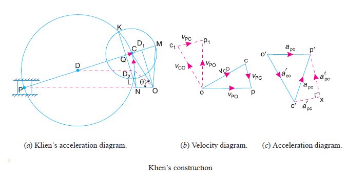
14. Klein’s Construction
A graphical method to find the velocity and acceleration of components in a slider crank mechanism.
Steps:
- Draw the kinematic diagram.
- Apply vector addition for velocities and accelerations.
- Construct velocity and acceleration polygons.
Unit 2: Friction and Lubrication
1. Dry Friction
Dry Friction: The resistance to motion when two solid surfaces slide over each other, without any lubrication.
- Static Friction: The frictional force that resists the initiation of motion.
- Kinetic Friction: The frictional force that resists the relative motion once motion has started.
- Laws of Dry Friction:
- The force of friction is directly proportional to the normal force.
- The force of friction is independent of the area of contact.
- Static friction is generally greater than kinetic friction.
2. Friction between Nut and Screw
In applications like power screws, friction plays a critical role in efficiency and energy loss.
Types of Threads:
- Square Thread: Higher efficiency due to lower friction, used in power transmission.
- Acme Thread: Easier to manufacture and more robust compared to square threads, but has higher friction.
3. Uniform Wear and Uniform Pressure Theory
Uniform Wear Theory:
Assumes that wear is uniformly distributed over the contact area. The frictional force is inversely proportional to the radius of contact.
- F = Friction force
- μ = Coefficient of friction
- W = Load
- R = Radius
Uniform Pressure Theory:
Assumes that the pressure is uniformly distributed over the entire contact area. The friction force is calculated as:
4. Friction at Pivot and Collars
Friction occurs at the contact surfaces of pivot bearings and collar bearings due to axial loads.
- Pivot Bearings: Support axial loads with rotational motion.
- Collar Bearings: Used in shafts where axial loads are present along with rotational motion.
The friction torque for a flat pivot bearing is calculated using the uniform pressure and wear theories.
5. Friction in Turning Pair
In turning pairs (revolute joints), friction resists rotational motion between the two contacting surfaces. The magnitude of friction depends on the normal force and the nature of the surfaces in contact.
6. Friction Circle and Friction Axis

Friction Circle: A graphical tool used in the analysis of mechanisms with turning pairs. It represents the limit of the force that can be transmitted before slipping occurs due to friction.
Friction Axis: The line along which the frictional force acts in a mechanism. This helps in analyzing the direction and magnitude of the friction forces.
7. Friction in Mechanisms
Friction plays an important role in various mechanical systems. It affects efficiency, power transmission, and wear. Common mechanisms influenced by friction include cams, gears, and bearings.
8. Lubrication
Lubrication: The process of introducing a substance (lubricant) between two surfaces to reduce friction and wear.
- Purpose: To reduce friction, wear, and temperature rise due to contact between moving surfaces.
- Types:
- Boundary Lubrication: Occurs when the lubricating film is very thin, and there is direct contact between the surfaces.
- Thick Film Lubrication: A thick layer of lubricant separates the surfaces, preventing direct contact and reducing friction significantly.
9. Viscosity
Viscosity: A measure of a fluid’s resistance to flow. It is the property that governs the lubricant’s ability to reduce friction between surfaces.
The viscosity of a lubricant depends on temperature, with higher temperatures generally reducing viscosity.
10. Viscous Flow
Viscous Flow: The type of flow where frictional forces between fluid layers affect the motion of the fluid. In lubrication, viscous flow allows the formation of a thin film between moving surfaces, reducing friction.
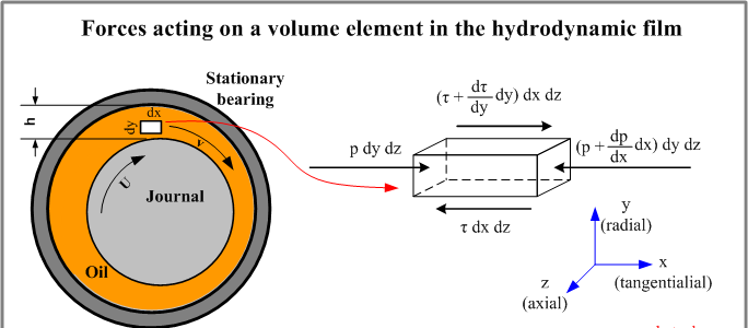
11. Hydrostatic and Hydrodynamic Lubrication
- Hydrostatic Lubrication: A lubricant is supplied under pressure from an external source, creating a separating film between surfaces.
- Hydrodynamic Lubrication: The motion of the surfaces generates a pressure that forms a film of lubricant between them, preventing direct contact.
Unit 3: Clutch, Brakes, and Dynamometers
1. Friction Clutches
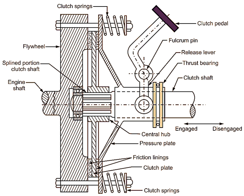
A clutch is a mechanical device that engages and disengages power transmission, especially from a driving shaft to a driven shaft. The clutch operates based on the friction between the contacting surfaces.
1.1 Single Plate Clutch
A single plate clutch consists of two main parts: the clutch plate and the pressure plate. When the clutch is engaged, friction between the clutch plate and the flywheel transfers the engine’s power to the transmission.
Torque Transmitting Capacity: The torque capacity of a single-plate clutch is given by:
- μ = Coefficient of friction
- W = Axial force (load)
- R = Mean radius of the contact surface
1.2 Multi-Plate Clutch
Multi-plate clutches consist of multiple clutch plates between the flywheel and the pressure plate, increasing the torque transmitting capacity for the same space.
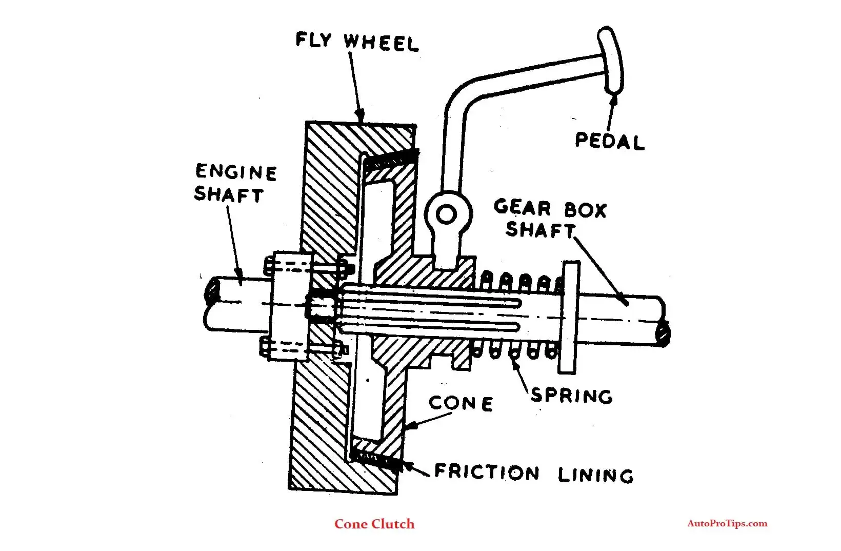
1.3 Cone Clutch
In a cone clutch, the contact surfaces are conical, increasing the frictional surface area and thus allowing more torque transmission. The torque capacity is given by:
- α = Semi-angle of the cone
1.4 Centrifugal Clutch
A centrifugal clutch automatically engages as the engine speed increases. It works based on the centrifugal force exerted by the rotating weights, which forces the clutch shoes outward to engage the drum.
2. Clutch Operating Mechanism
The clutch operating mechanism includes the pedal, lever, release bearing, and other components that allow the driver to engage or disengage the clutch. The mechanical or hydraulic system transfers the driver’s input to the clutch system.
3. Brakes
Brakes are used to slow down or stop the motion of a vehicle or machine by applying friction to a moving part.
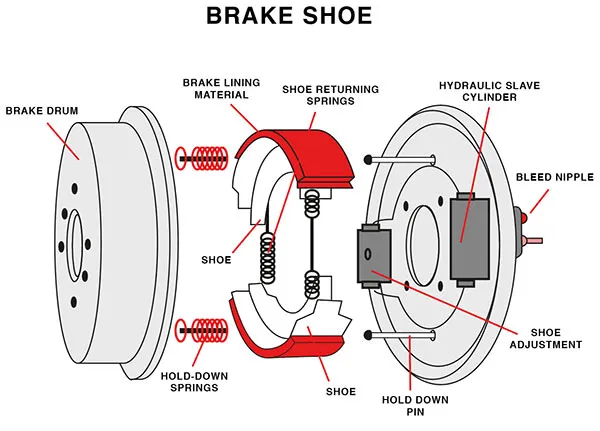
3.1 Shoe Brake
A shoe brake consists of a brake shoe that presses against a drum or disc. There are two types of shoe brakes:
- Internal Shoe Brakes: The brake shoes press outward against the inner surface of a rotating drum.
- External Shoe Brakes: The brake shoes press inward against the outer surface of the rotating drum.
3.2 Block Brake
In block brakes, a block or shoe is applied to a rotating wheel or drum to generate friction and bring the wheel to rest.
3.3 Band Brake
A band brake consists of a flexible band or strap that tightens around a rotating drum to slow it down. The braking torque is proportional to the tension in the band and the radius of the drum.
3.4 Band and Block Brake
This type of brake combines both band and block principles to increase the braking force.
3.5 Braking Torque
The braking torque for a shoe or block brake can be calculated using the following formula:
- μ = Coefficient of friction
- W = Normal force
- R = Radius of the drum or wheel
4. Dynamometers
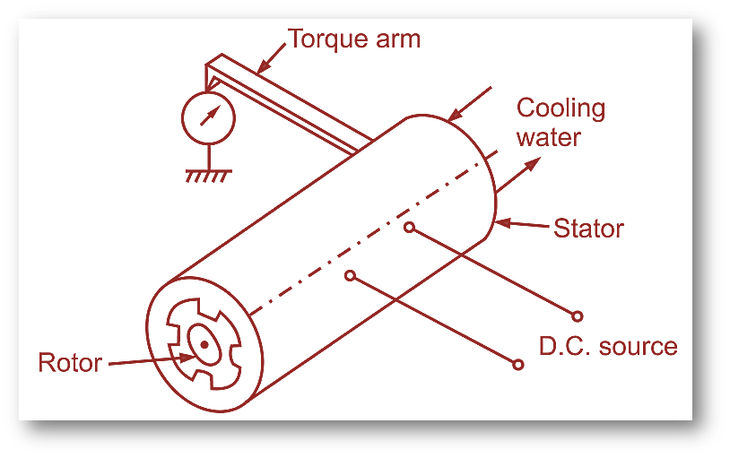
A dynamometer is a device used to measure the power output or torque of an engine or machine.
4.1 Types of Dynamometers
- Absorption Dynamometers: Measure torque by absorbing energy through friction or other means.
- Transmission Dynamometers: Measure torque while transmitting energy without absorbing it.
4.2 Eddy Current Dynamometer
In an eddy current dynamometer, a magnetic field induces eddy currents in a rotating disk or drum. The interaction between the magnetic field and the eddy currents generates a resistive force, which is proportional to the torque applied.
5. Torque Measurement
Torque measurement in dynamometers is based on the resistive force generated by the machine being tested. The torque can be calculated using:
- F = Force measured by the dynamometer
- R = Radius at which the force is applied
Unit 4: Cams and Followers
1. Types of Cams and Followers
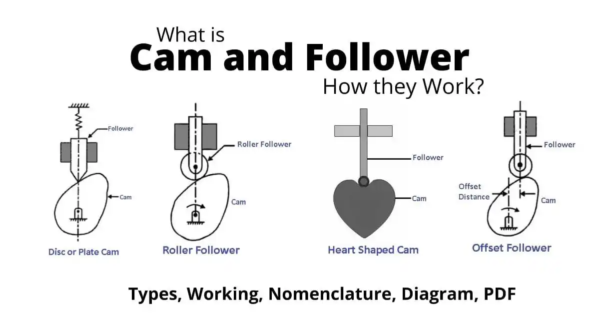
A cam is a mechanical device that converts rotational motion into linear motion. It is typically used in engines and machines where a rotating motion is converted into a specific movement of a follower. The follower is a component that rides on the cam profile and moves according to the cam’s shape.
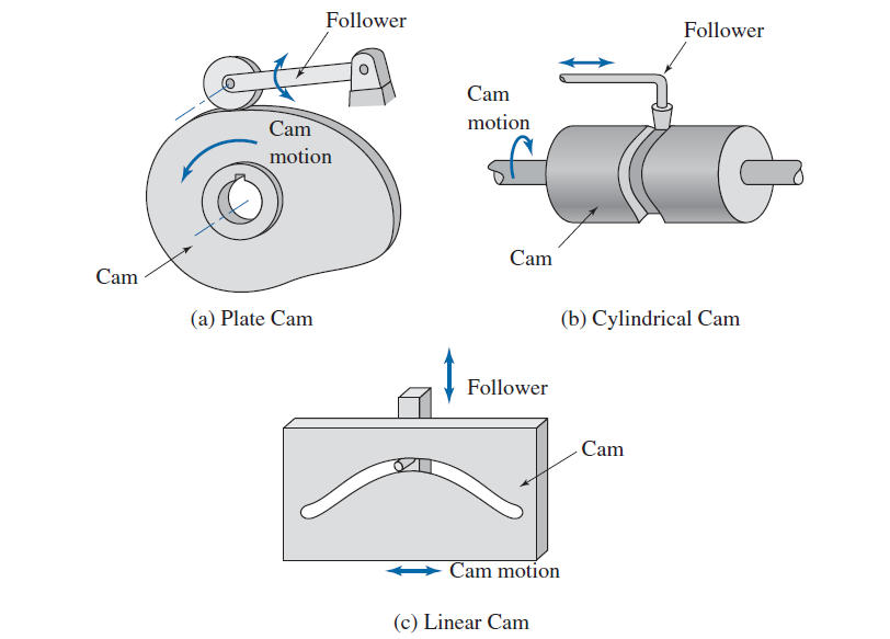
1.1 Types of Cams
- Disk or Plate Cam: A cam where the profile is cut on a disk or plate.
- Cylindrical Cam: A cam in which the profile is cut on a cylindrical surface.
- Translating Cam: A cam that moves linearly while driving a follower.
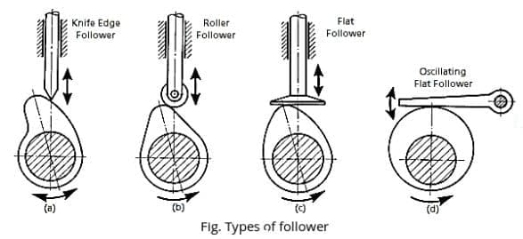
1.2 Types of Followers
- Knife Edge Follower: The follower has a sharp edge in contact with the cam surface.
- Roller Follower: The follower has a rolling element in contact with the cam to reduce friction.
- Flat Follower: The follower has a flat surface that contacts the cam.
- Spherical Follower: The follower has a spherical surface for contact with the cam.
2. Analysis of Motion
When designing cam profiles, the motion of the follower must be analyzed to achieve the desired movement. There are different types of follower motion:
- Uniform Motion: The follower moves at a constant velocity.
- Simple Harmonic Motion (SHM): The follower moves in harmonic motion with respect to the cam rotation.
- Uniform Acceleration and Deceleration: The follower moves with uniform acceleration during one part of the cam profile and uniform deceleration during the other part.
3. Jump and Ramp of Cam
Jump and ramp refer to the sudden rise and gradual descent of the follower. A properly designed ramp ensures smooth acceleration and deceleration of the follower to avoid impact.
4. Determination of Cam Profiles
Cam profiles are determined based on the motion of the follower. The following equations are typically used to analyze cam profiles:
- θ = Cam angle
- ω = Angular velocity
- t = Time
The cam profile is then plotted based on the required motion of the follower.
5. Types of Cams Based on Profiles
5.1 Circular Arc Cam
A circular arc cam has a profile shaped like a segment of a circle. The motion of the follower is determined by the radius of the arc and the angular displacement of the cam.
5.2 Tangent Cam
In tangent cams, the follower moves in a straight line until it reaches a tangent point, after which it follows a curved path. These cams are used when the follower needs to move linearly over part of its motion.
5.3 Cycloidal Cam
A cycloidal cam is designed using a cycloidal curve. This type of cam provides smooth acceleration and deceleration to the follower, making it ideal for applications that require minimal wear and smooth motion.

6. Velocity and Acceleration Analysis
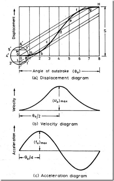
Velocity and acceleration analysis of cams is done to ensure that the follower’s motion is smooth and doesn’t result in excessive forces or jerks. The relative velocity and acceleration between the cam and the follower can be calculated using the following expressions:
- V_f = Follower velocity
- r = Radius of the cam profile
- ω = Angular velocity of the cam
Cams and followers play a crucial role in many mechanical systems, especially in engines and manufacturing equipment. The design and analysis of cam profiles ensure smooth motion and efficient operation. Proper attention to the type of cam, follower, and the required motion is essential for the successful design of cam mechanisms.
Unit 5: Balancing
1. Balancing of Rotating Masses
Balancing is the process of distributing the masses in a machine to ensure that forces and moments are equalized, preventing vibrations. Unbalanced rotating masses can cause harmful vibrations that reduce machine life and efficiency.
1.1 Balancing in One Plane
If all rotating masses are in a single plane, balancing can be achieved by introducing a mass that compensates for the unbalanced forces. The resultant force in the system must be zero for proper balancing.
1.2 Balancing in Several Planes
When the rotating masses are distributed across several planes, balancing requires both force and moment balancing. Each plane contributes to the total unbalanced forces and moments, which need to be resolved to ensure smooth operation.
2. Balancing of Reciprocating Masses
In engines with reciprocating masses (e.g., pistons and connecting rods), the balancing process involves minimizing the unbalanced forces produced by these moving parts. Engines with single and multi-cylinder arrangements, such as inline, V-type, and radial engines, need special consideration.
2.1 Single-Cylinder Engines
In a single-cylinder engine, complete balancing is impossible due to the reciprocating motion of the piston. However, partial balancing can be achieved by balancing the rotating masses to reduce the impact of the unbalanced forces.
2.2 Multi-Cylinder Engines
In multi-cylinder engines, the arrangement of cylinders plays a key role in balancing. Some common configurations include:
- Inline Engines: Cylinders are arranged in a straight line. Balancing involves managing both primary and secondary forces.
- V-Type Engines: Cylinders are arranged in a V-shape, offering better balancing compared to inline engines.
- Radial Engines: Cylinders are arranged around a central crankshaft, often used in aircraft engines. These engines offer good balancing properties.
3. Primary and Secondary Balancing Analysis
The forces generated by reciprocating masses can be divided into primary and secondary forces:
- Primary Forces: These forces result from the basic reciprocating motion of the masses and are proportional to the speed of the crankshaft.
- Secondary Forces: These forces arise from the complex motion of the connecting rod and are proportional to the square of the crankshaft speed.
4. Concept of Direct and Reverse Cranks
The method of direct and reverse cranks is used to analyze reciprocating systems. In this method, the motion of a reciprocating mass is considered equivalent to the motion of two rotating masses, one rotating in the same direction (direct crank) and the other in the opposite direction (reverse crank).
5. Balancing of Locomotive Engines
In locomotive engines, balancing is crucial to ensure smooth operation at high speeds. These engines typically use large reciprocating masses, which require careful balancing to avoid excessive wear and vibrations.
6. Effect of Partial Balancing
Partial balancing occurs when only part of the unbalanced mass is compensated for. While this reduces the overall unbalance, it can still result in some vibrations. Partial balancing is often used in situations where full balancing is impractical or unnecessary.
7. Static and Dynamic Balancing
Static and dynamic balancing are two types of balancing techniques:
- Static Balancing: Achieved when the mass center of a rotating object is on its axis of rotation. This ensures the object stays at rest in any orientation.
- Dynamic Balancing: Achieved when both the mass center and the moments about the axis of rotation are balanced. This ensures smooth operation even at high speeds.

8. Important Equations
The following are important equations used in balancing analysis:
- m_1 and m_2 are the masses
- r_1 and r_2 are the radii of rotation
- F = Centrifugal force
- m = Mass
- r = Radius of rotation
- ω = Angular velocity
Balancing is a critical aspect of machine design, especially in engines and rotating machinery. Proper balancing reduces vibrations, increases the lifespan of components, and ensures smoother operation. Understanding the concepts of static and dynamic balancing, as well as the principles behind the balancing of rotating and reciprocating masses, is essential for effective machine design.
Text Books:
- A. Ghosh, A. K. Malik, “Theory of Mechanisms and Machines”, Affiliated East-West Press Pvt. Ltd., New Delhi.
- S. S. Rattan, “Theory of Machines”, Tata McGraw Hill, New Delhi.
References:
- Thomas Beven, “Theory of Machines”, CBS Publishers and Distributors, Delhi.
- J. E. Shigley, J. J. Uicker, “Theory of Machines and Mechanisms”, Tata McGraw Hill Publications, New York, International Student Edition, 1995.
