Strength of Material
Unit 1: Simple Stresses and Strains
1. Mechanical Properties of Materials
Mechanical properties describe how materials respond to various forces and loads. Key properties include:
- Tensile Strength: The maximum stress a material can withstand while being stretched or pulled before breaking.
- Compressive Strength: The ability of a material to resist compression or squashing forces.
- Shear Strength: The resistance to forces that cause the material to slide against itself.
- Elasticity: The ability of a material to return to its original shape after deformation.
- Plasticity: The ability of a material to permanently deform without breaking.
- Brittleness: A material’s tendency to fracture or break with little to no plastic deformation.
- Ductility: The ability of a material to stretch into a wire.
- Malleability: The ability of a material to deform under compressive stress, often resulting in a thin sheet.
2. Analysis of Internal Forces
Internal forces develop within a material when external forces are applied. These forces include:
- Tensile Force: Force that pulls and elongates the material.
- Compressive Force: Force that compresses or shortens the material.
- Shear Force: Force that causes sliding or shearing within the material.
3. Simple Stresses and Strains
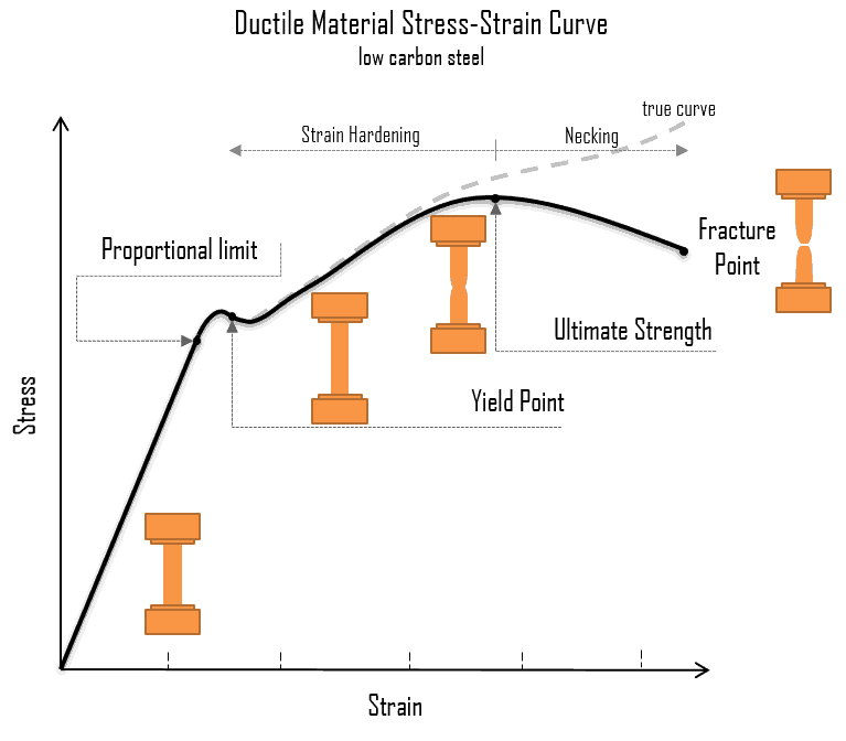
- Purpose: To understand the behavior of materials under load, showing the relationship between stress and strain.
- Key Points:
- Elastic Region (follows Hooke’s Law).
- Yield Point (where plastic deformation begins).
- Ultimate Tensile Strength (maximum stress before necking).
- Fracture Point (failure).
- Materials: Different materials (like steel, aluminum, rubber) have unique stress-strain curves. For metals, this curve typically shows a linear portion followed by yielding and failure.
Stress is defined as the force per unit area within materials. Mathematically:
σ = F / A where σ = stress, F = applied force, and A = cross-sectional area.
Strain is the measure of deformation caused by applied stress. Strain is dimensionless and is given by:
ε = δ / L where ε = strain, δ = change in length, and L = original length.
Types of Stress
- Tensile Stress: Caused by forces that pull the material.
- Compressive Stress: Caused by forces that push or compress the material.
- Shear Stress: Caused by forces acting parallel to the material’s surface.
Types of Strain
- Longitudinal Strain: The change in length per unit length in the direction of the applied force.
- Lateral Strain: The change in dimensions perpendicular to the direction of the applied force.
- Shear Strain: The angular deformation caused by shear stress.
4. Stress-Strain Curve
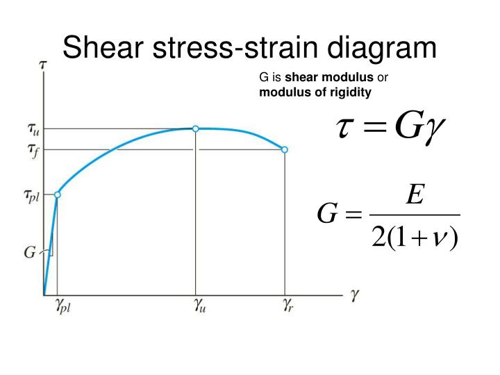
- Purpose: To represent how a material behaves when subjected to shear forces.
- Key Points:
- Similar to the tensile stress-strain diagram but represents shear forces.
- The slope in the elastic region is determined by the shear modulus (G)
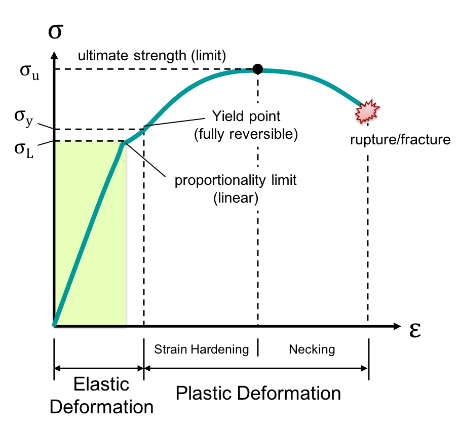
The stress-strain curve illustrates how a material behaves under tensile stress. Key points on the curve include:
- Proportional Limit: The point up to which stress is directly proportional to strain (Hooke’s Law applies).
- Elastic Limit: The maximum stress a material can withstand and still return to its original shape.
- Yield Point: The point at which the material starts to deform plastically.
- Ultimate Tensile Strength (UTS): The maximum stress a material can withstand.
- Fracture Point: The point at which the material breaks.
5. Hooke’s Law
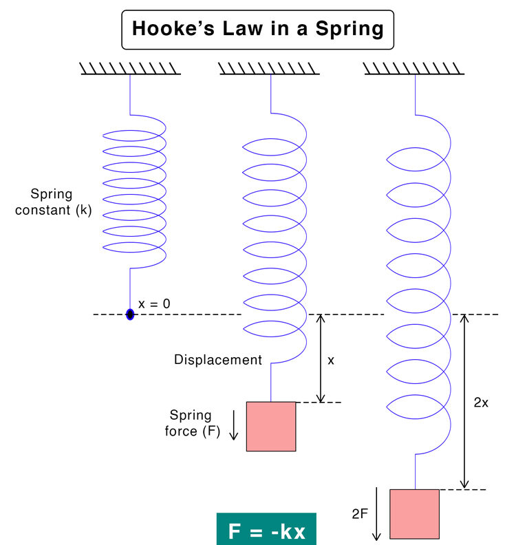
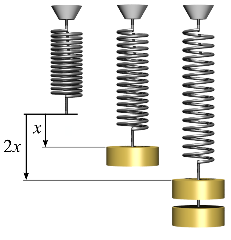
- Purpose: To show the relationship between stress and strain in the elastic region (following Hooke’s Law).
- Key Points:
- Stress is proportional to strain in the elastic region, represented by the linear portion of the stress-strain curve.
- The slope of this linear region is the Modulus of Elasticity (E).
Hooke’s Law states that within the elastic limit, stress is directly proportional to strain. It is represented by:
σ = E * ε where σ = stress, ε = strain, and E = Young’s Modulus of Elasticity.
6. Modulus of Elasticity
The modulus of elasticity (Young’s Modulus) measures the stiffness of a material. It is defined as the ratio of stress to strain in the elastic region of the stress-strain curve.
7. Thermal Stress
Thermal stress occurs when a material expands or contracts due to changes in temperature. If the material is constrained, it experiences stress. The thermal stress is given by:
σ = α * E * ΔT where α = coefficient of thermal expansion, E = modulus of elasticity, and ΔT = change in temperature.
8. Hoop Stress
Hoop stress is the stress exerted circumferentially in a cylindrical or spherical object due to internal pressure. It is calculated as:
σ_h = (p * r) / t where p = internal pressure, r = radius of the cylinder, and t = wall thickness.
9. Poisson’s Ratio
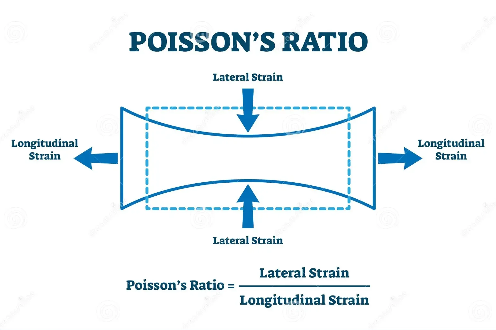
Poisson’s ratio is the ratio of lateral strain to longitudinal strain:
ν = - ε_lat / ε_long where ν = Poisson’s ratio, ε_lat = lateral strain, and ε_long = longitudinal strain.
10. Volumetric Stress and Bulk Modulus
Volumetric stress occurs when an object experiences equal stress in all directions. The bulk modulus (K) is a measure of a material’s resistance to uniform compression and is given by:
K = (σ_v / ΔV / V) where σ_v = volumetric stress, ΔV = change in volume, and V = original volume.
11. Shear Modulus
The shear modulus (G) is the ratio of shear stress to shear strain:
G = (τ / γ) where τ = shear stress, and γ = shear strain.
12. Relationship between Elastic Constants
The relationship between elastic constants (E, G, and K) is given by:
E = 2G(1 + ν)
E = 3K(1 - 2ν)
13. Principal Stresses and Strains
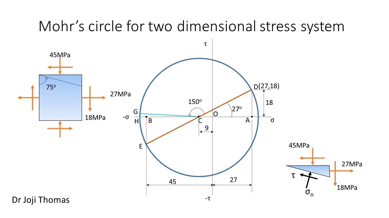
Principal stresses are the maximum and minimum normal stresses acting on a plane where shear stress is zero. These are found by solving for the roots of the following equation:
σ_p = (σ_x + σ_y) / 2 ± sqrt[((σ_x - σ_y) / 2)^2 + τ_xy^2]
Principal Strains
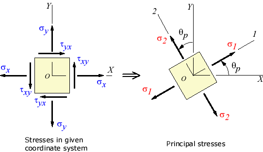
Principal strains are the maximum and minimum normal strains on a plane. They are found similarly to principal stresses by solving strain transformation equations.
14. Strain Rosettes
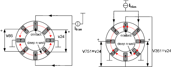
A strain rosette is a device used to measure strains in multiple directions. By measuring strain in three directions, principal strains can be determined, and stresses can be calculated using the strain transformation equations.
15. Shear Strains
Shear strains measure the angular distortion caused by shear stress. The angle of distortion is represented by γ, and shear strain is related to shear stress by:
τ = G * γ where τ = shear stress, G = shear modulus, and γ = shear strain.
Understanding the concepts of stresses, strains, and their relationships is critical in material mechanics. These principles are applied in design and analysis to ensure that structures and materials can withstand forces without failure.
Unit 2: Strain Energy, Resilience, and Combined Stresses
1. Strain Energy and Resilience
Strain energy is the energy stored in a body due to deformation when subjected to external forces. It is given by:
U = ½ * σ * ε * V
Where U is strain energy, σ is stress, ε is strain, and V is the volume of the body.
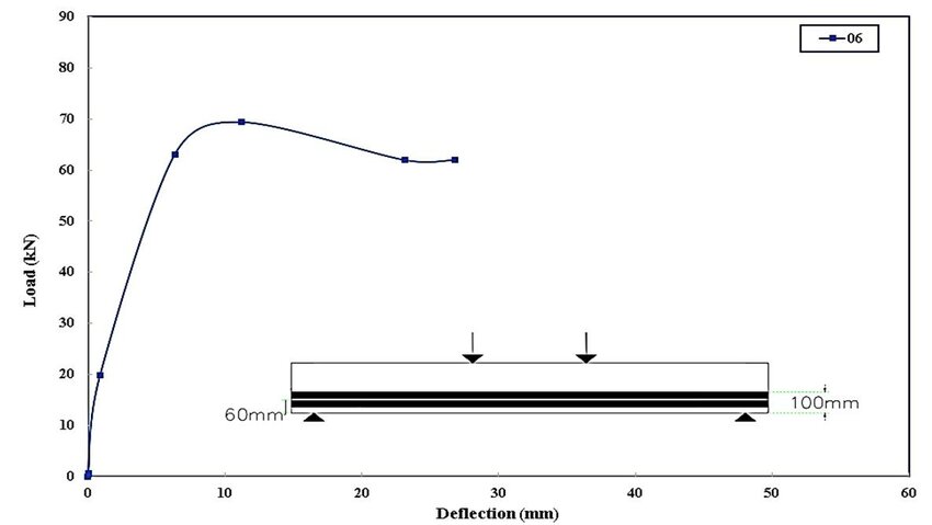
Load-Deflection Diagram
The load-deflection diagram represents the relationship between the applied load and the resulting deflection in a structure. The area under the load-deflection curve represents the strain energy stored in the material.
Proof Resilience
Proof resilience is the maximum strain energy stored in a material without causing permanent deformation. It is given by:
U_proof = ½ * σ_y^2 / E
Where σ_y is the yield stress and E is the modulus of elasticity.
Stresses Due to Gradual, Sudden, and Impact Loadings
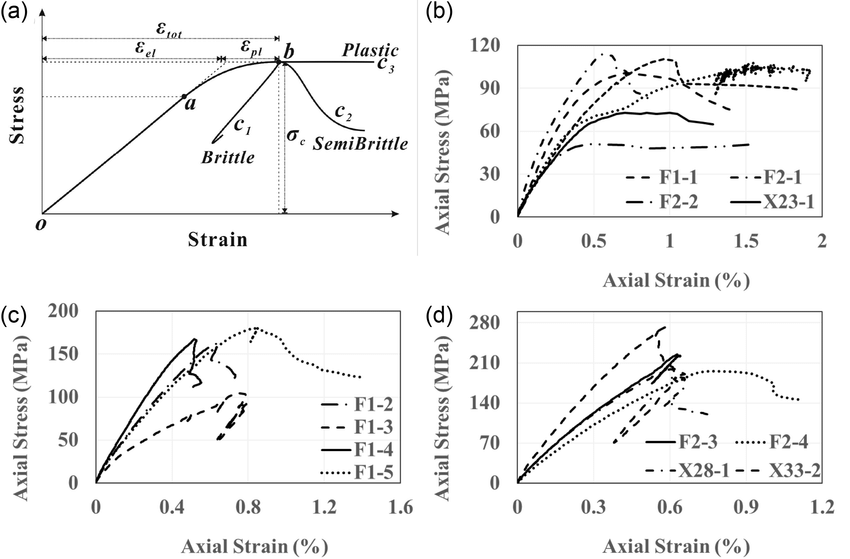
- Gradual Loading: Load is applied slowly, allowing the material to gradually respond to the stress. The stress is proportional to the applied load.
- Sudden Loading: Load is applied instantly, causing a doubling of stress compared to gradual loading for the same deformation.
- Impact Loading: Load is applied with velocity, and the resulting stress is significantly higher. The stress can be calculated using the energy balance method.
Shear Resilience
Shear resilience refers to the material’s ability to resist shear forces and store energy without undergoing permanent deformation. It is given by:
U_shear = ½ * τ^2 / G
Where τ is the shear stress, and G is the shear modulus.
2. Combined Stresses
Combined axial and flexural loads occur when both axial forces (tensile or compressive) and bending moments act on a member. The combined stress at any point in a section is the sum of direct and bending stresses, given by:
σ_combined = σ_axial ± σ_bending
Middle Third Rule
The Middle Third Rule is used in masonry structures to ensure that no tensile stresses occur. It states that the resultant force of a load must lie within the middle third of the section to avoid tension.
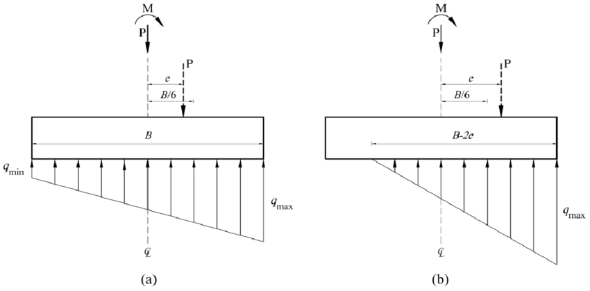
- Middle third rule ensures no tensile stress develops if the load is within the middle third of the section.
- Kernel of a section defines the area within which the load must lie to avoid tension in any part of the section.
- Critical for designing columns, beams, and foundations to avoid failure.
Kernel of a Section
The kernel of a section refers to the area within a section where an eccentric load can be applied without causing tensile stresses. For rectangular sections, the kernel is the middle third of the cross-sectional area.
Eccentrically Applied Load
When a load is applied away from the centroid of a section, it is known as an eccentric load. Eccentrically applied loads cause both direct and bending stresses, and the resulting stress distribution is non-uniform across the section.
3. Columns and Struts
Columns are vertical members subjected to compressive loads, while struts are inclined or horizontal members subjected to compressive forces. Columns can be classified into short and long columns based on their length and slenderness ratio.
Short and Long Columns
- Short Columns: Fail due to material strength (crushing) under axial load.
- Long Columns: Fail due to buckling, which is a function of length and slenderness ratio.
Euler’s Formula
Euler’s formula is used to calculate the critical load at which long columns buckle. It is given by:
P_cr = (π^2 * E * I) / (L^2)
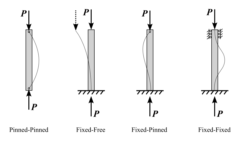
Where P_cr is the critical load, E is the modulus of elasticity, I is the moment of inertia, and L is the length of the column.
Rankine’s Formula
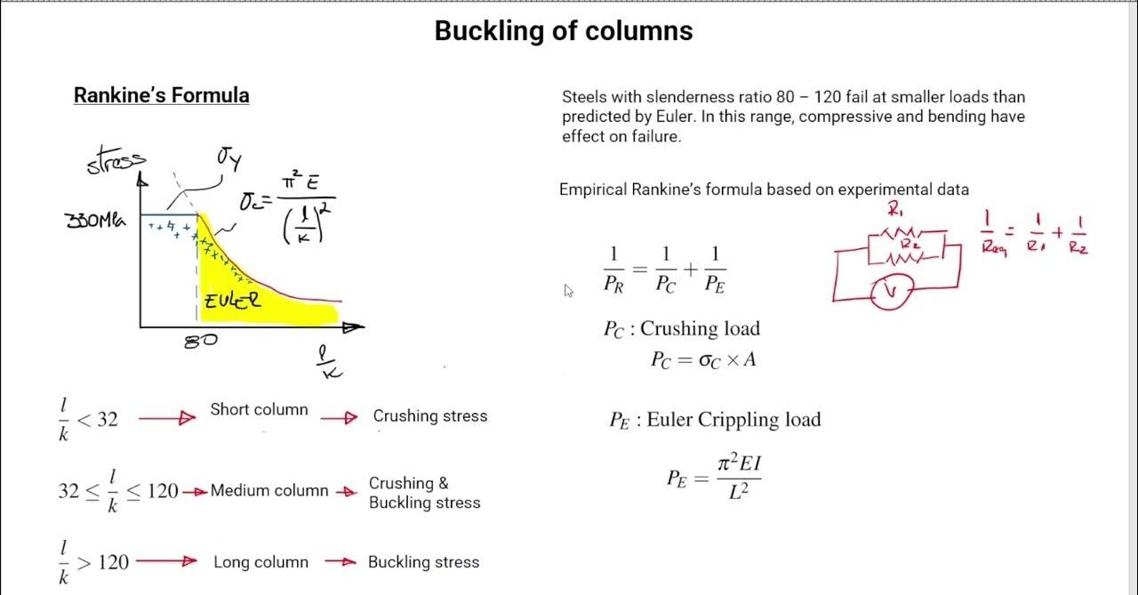
Rankine’s formula is used to account for both crushing and buckling in short and long columns. It is given by:
P_cr = (σ_c * A) / (1 + (α * (L/K)^2))
Where σ_c is the crushing stress, A is the cross-sectional area, α is an empirical constant, L is the length of the column, and K is the radius of gyration.
Limitation of Euler’s Formula
Euler’s formula is valid only for long, slender columns and does not account for short columns where material strength governs failure. For short columns, Rankine’s formula provides a more accurate prediction of failure load.
Equivalent Length
Equivalent length of a column is the distance between two points of zero moment (where the column bends). It depends on the boundary conditions and is given by:
- Both ends pinned:
L_eq = L - Both ends fixed:
L_eq = L/2 - One end fixed, one end free:
L_eq = 2L - One end fixed, one end pinned:
L_eq = L/√2
Eccentrically Loaded Short Compression Members
In eccentrically loaded short compression members, the load is applied off the centroid, causing both axial and bending stresses. The resulting stress distribution can be calculated by superimposing the direct and bending stresses.
This unit covers critical concepts related to strain energy, resilience, and combined stresses. Understanding these topics is essential for analyzing structural members under various loading conditions and determining their capacity to resist deformation and failure.
Unit 3: Stresses in Beams
1. Moment of Inertia of Different Sections
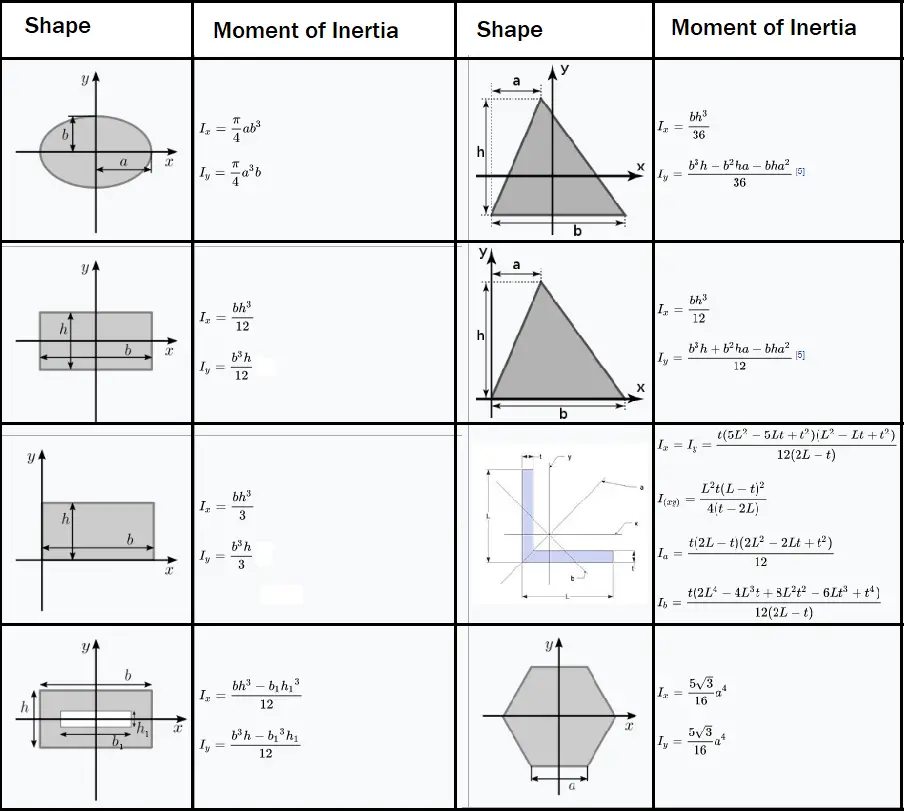
Moment of inertia (I) is a property of a section that helps in determining its resistance to bending and torsion. It depends on the geometry of the cross-section.
- Rectangular section:
I = (b * h^3) / 12where b = base width, h = height. - Circular section:
I = (π * d^4) / 64where d = diameter. - I-section: The moment of inertia for an I-section is derived by breaking the section into simpler rectangular components and applying the parallel axis theorem.
2. Bending and Shearing Stresses in a Beam
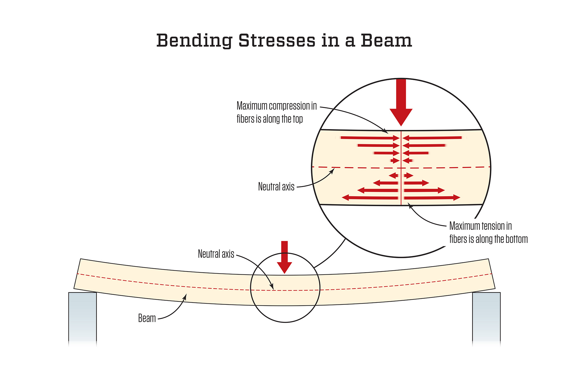
Bending stress in a beam arises due to the applied moment, causing the beam to bend. The bending stress at any point is given by the flexural formula:
σ = (M * y) / I
Where:
- σ = Bending stress
- M = Moment
- y = Distance from the neutral axis
- I = Moment of inertia of the section
Theory of Simple Bending
The theory of simple bending assumes that:
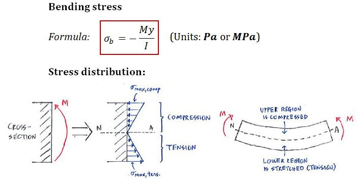
- Flexural formula: σ=M⋅y/I
- The material of the beam is homogeneous and isotropic.
- The beam has a constant cross-section along its length.
- Plane sections remain plane after bending.
- The bending occurs only due to moments applied in the plane of the beam’s cross-section.
Economic Sections
Economic sections are cross-sectional shapes that provide maximum strength while minimizing material usage. The I-section is considered economical due to its high moment of inertia relative to its weight.
Shear Stress in Beams
Shear stress in beams occurs due to transverse loads. The shear stress at any point is given by the formula:
τ = (V * Q) / (I * b)
Where:
- τ = Shear stress
- V = Shear force
- Q = First moment of area
- I = Moment of inertia of the section
- b = Width of the section at the point of interest
Shear Stress Distribution for Different Sections
The distribution of shear stress across a beam’s cross-section varies depending on the section geometry:
- Rectangular Section: Shear stress is maximum at the neutral axis and zero at the top and bottom surfaces. It follows a parabolic distribution.
- Solid Circular Section: The shear stress distribution is parabolic, with maximum shear stress at the neutral axis and zero at the outer surface.
- I-Section: Shear stress is concentrated more in the web than in the flanges.
3. Design for Flexure and Shear
When designing beams for flexure, the following factors are considered:
- Flexural strength: The beam must resist bending moments without yielding.
- Shear strength: The beam must resist shear forces without failing in shear.
- Material properties: The strength of the material plays a crucial role in determining the section size and shape.
Torsion
1. Introduction and Assumptions
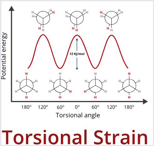
Torsion occurs when a moment or torque is applied to a member causing it to twist about its longitudinal axis. Torsional stress and deformation are analyzed using the following assumptions:
- The material is homogeneous and isotropic.
- The cross-sections remain plane and circular after twisting.
- The twist along the length of the shaft is uniform.
2. Derivation of Torsion Formula
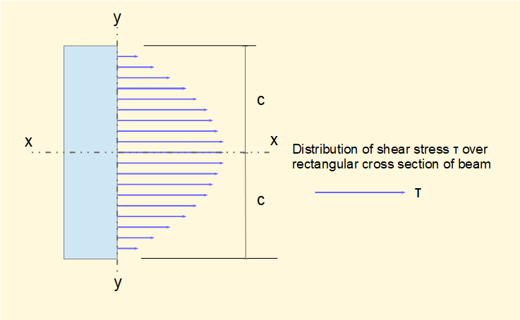
The torsion formula relates the applied torque to the resulting shear stress in the shaft:
τ = (T * r) / J
Where:
- τ = Shear stress
- T = Applied torque
- r = Distance from the center to the point of interest
- J = Polar moment of inertia
Polar Moment of Inertia for Circular Sections
The polar moment of inertia (J) for solid and hollow circular sections is:
- Solid circular shaft:
J = (π * d^4) / 32 - Hollow circular shaft:
J = (π * (d_o^4 - d_i^4)) / 32
3. Torsion of Circular Shafts
Circular shafts under torsion experience shear stress, which is distributed linearly from zero at the center to a maximum at the outer surface. The angle of twist (θ) is given by:
θ = (T * L) / (G * J)
Where:
- θ = Angle of twist
- T = Applied torque
- L = Length of the shaft
- G = Modulus of rigidity
- J = Polar moment of inertia
4. Indeterminate Solid/Homogeneous/Composite Shafts
For indeterminate shafts (solid, homogeneous, or composite), the torsional analysis is performed by considering equilibrium conditions and compatibility of deformation. The total torque is distributed based on the stiffness of each component.
5. Torsional Strain Energy
Torsional strain energy is the energy stored in a shaft due to twisting and is given by:
U = ½ * (T^2 * L) / (G * J)
Where:
- U = Torsional strain energy
- T = Applied torque
- L = Length of the shaft
- G = Modulus of rigidity
- J = Polar moment of inertia
In this unit, we studied the behavior of beams under bending and shearing stresses and shafts under torsion. Understanding the distribution of stresses and the factors affecting flexure and shear is crucial for the design of safe and efficient structural members.
Unit 4: Shear Force and Bending Moment Diagrams
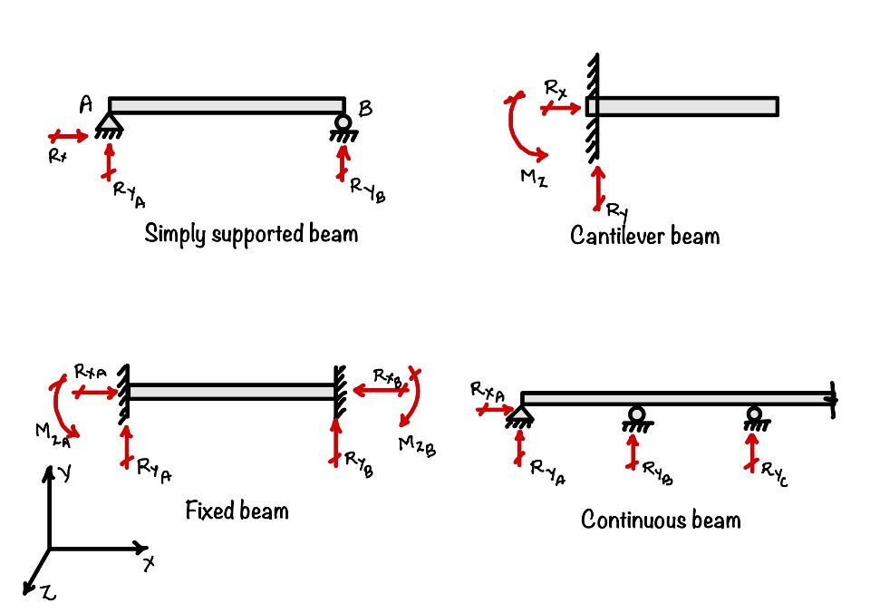
1. Introduction to Different Types of Beams
Beams are classified based on their supports and loading conditions:
- Cantilever Beam: A beam fixed at one end and free at the other.
- Simply Supported Beam: A beam supported at both ends, free to rotate but not to translate.
- Fixed Beam: A beam whose both ends are fixed, preventing rotation and translation.
- Overhanging Beam: A beam that extends beyond its support at one or both ends.
- Continuous Beam: A beam that spans over more than two supports.
2. Types of Supports & Loads
Beams can be subjected to different types of loads and supported in various ways:
- Supports:
- Roller Support: Allows free horizontal movement but restricts vertical movement.
- Hinged/Pinned Support: Prevents vertical and horizontal movement but allows rotation.
- Fixed Support: Restricts both rotation and translation in all directions.
- Loads:
- Concentrated Load (Point Load): A load applied at a specific point on the beam.
- Uniformly Distributed Load (UDL): A load that is spread evenly across a section of the beam, denoted as load per unit length (e.g., N/m).
- Uniformly Varying Load (UVL): A load that varies uniformly along the length of the beam, increasing or decreasing linearly.
- Couple: A pair of equal and opposite forces whose line of action does not coincide, causing a moment without any net force.
3. Concept and Definition of Shear Force and Bending Moment
Shear Force (SF): The internal force that resists the vertical movement of a beam section. It is the algebraic sum of all vertical forces acting on either side of the section.
Bending Moment (BM): The internal moment that resists bending at a beam section. It is the algebraic sum of moments of all forces acting on either side of the section.
4. Shear Force and Bending Moment Diagrams (SFD and BMD)
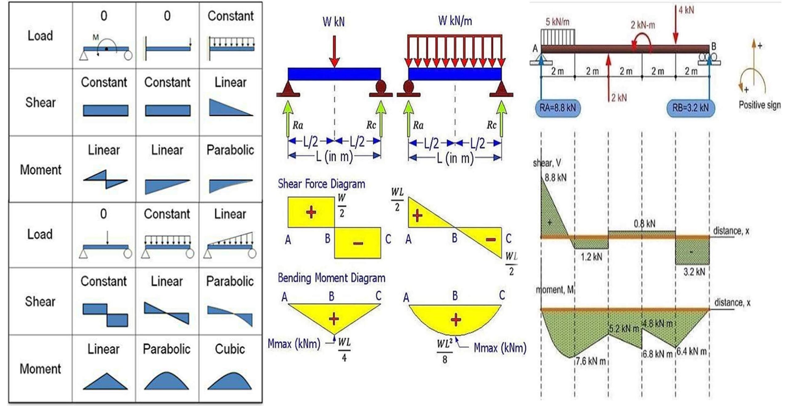
Shear Force and Bending Moment Diagrams are graphical representations of how shear forces and bending moments vary along the length of a beam under loading.

Types of Loadings Considered:
- Concentrated Loads: Point loads applied at specific positions on the beam.
- Uniformly Distributed Loads (UDL): Loads that are evenly distributed along a section of the beam.
- Uniformly Varying Loads (UVL): Loads that vary linearly across the beam’s length.
- Couples: Moments applied at specific points on the beam.
5. Relation Between Shear Force, Bending Moment, and Intensity of Loading
- Relationship Between Load and Shear Force:
The slope of the Shear Force Diagram (SFD) at any point is equal to the intensity of the distributed load at that point:
dV/dx = -w(x)wherew(x)is the load intensity at point x. - Relationship Between Shear Force and Bending Moment:
The slope of the Bending Moment Diagram (BMD) is equal to the shear force at that point:
dM/dx = V(x)whereV(x)is the shear force at point x. 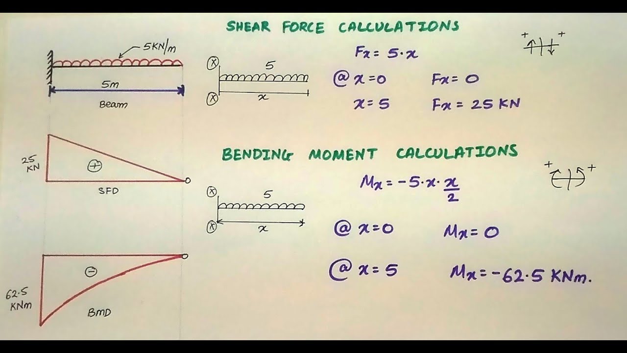
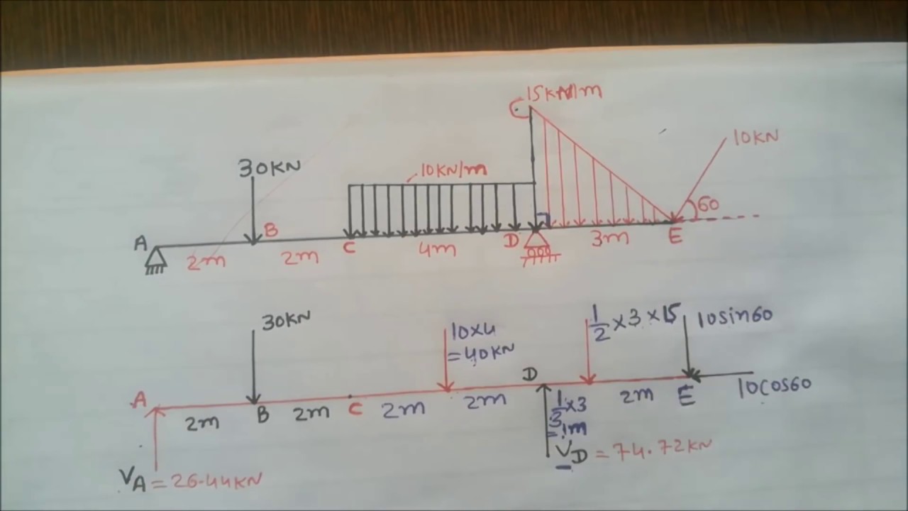
6. Construction of Shear Force and Bending Moment Diagrams
To construct SFD and BMD for beams under various loading conditions, follow these steps:
- Cantilever Beam:
For a cantilever beam under a concentrated load at the free end:
- Shear Force Diagram (SFD): The SF is constant along the length of the beam, starting at the free end and ending at the fixed end.
- Bending Moment Diagram (BMD): The BM increases linearly from zero at the free end to a maximum at the fixed end.
- Simply Supported Beam:
For a simply supported beam under a uniformly distributed load (UDL):
- SFD: The SF varies linearly along the length of the beam.
- BMD: The BM is parabolic, with a maximum at the center and zero at the supports.
- Compound Beams:
For beams with multiple loading conditions or discontinuities, construct the SFD and BMD by dividing the beam into sections and applying the principles of static equilibrium to each section.
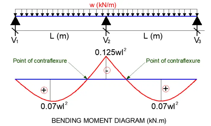
7. Critical and Maximum Values, Point of Contra Flexure
Critical Points: Locations on the beam where the shear force or bending moment reaches a maximum or changes sign. These are important for determining the beam’s design strength.
Point of Contra Flexure: The point on the beam where the bending moment changes sign (i.e., goes from positive to negative or vice versa). At this point, the beam experiences no bending moment and is neither in tension nor compression.
8. Construction of Bending Moment Diagram (BMD) from Shear Force Diagram (SFD)
The Bending Moment Diagram can be constructed from the Shear Force Diagram by integrating the shear force along the length of the beam. The slope of the BMD is equal to the value of the shear force at that point.
9. Construction of Load Diagram and SFD from BMD
To construct the load diagram and Shear Force Diagram from a Bending Moment Diagram:
- Determine the slope of the BMD to find the shear force.
- Use the relationship between shear force and load intensity to determine the loading condition.
- In this unit, we have explored the concepts of shear force and bending moment in beams, and learned how to construct and interpret Shear Force Diagrams and Bending Moment Diagrams for various beam configurations and loading conditions. Understanding these concepts is essential for the design and analysis of structural members under load.
Unit 5: Deflection of Beams
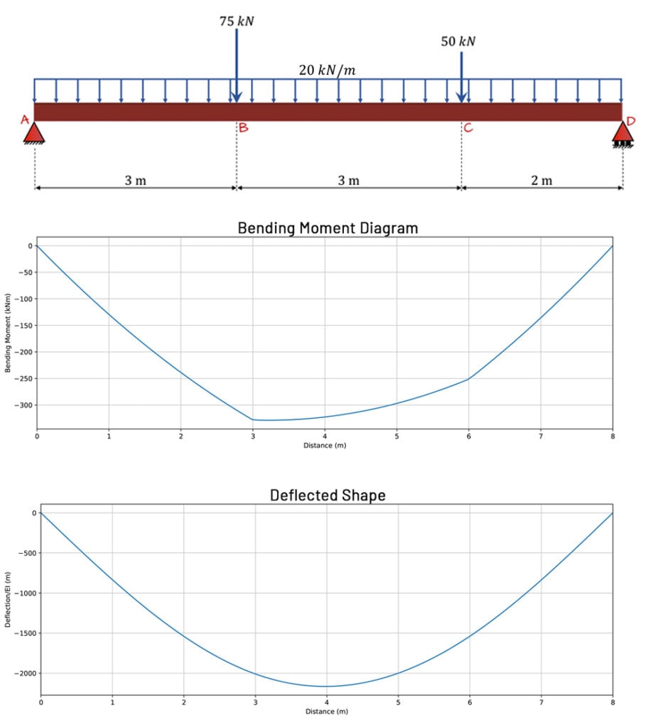
1. Differential Equation of Deflected Beam
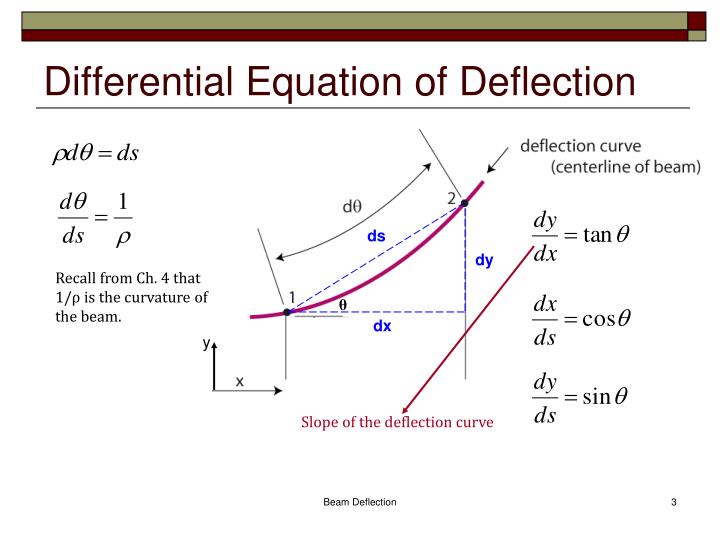
The deflection of a beam under a load can be determined using the differential equation of the deflected beam. The equation is derived from the relationship between the bending moment, curvature, and the beam’s material properties.
The general form of the differential equation is:
d2y/dx2 = -M(x) / (EI)
Where:
y= Deflection of the beam at a pointxM(x)= Bending moment at pointxE= Modulus of ElasticityI= Moment of Inertia of the beam’s cross-section
2. Slope and Deflection at a Point
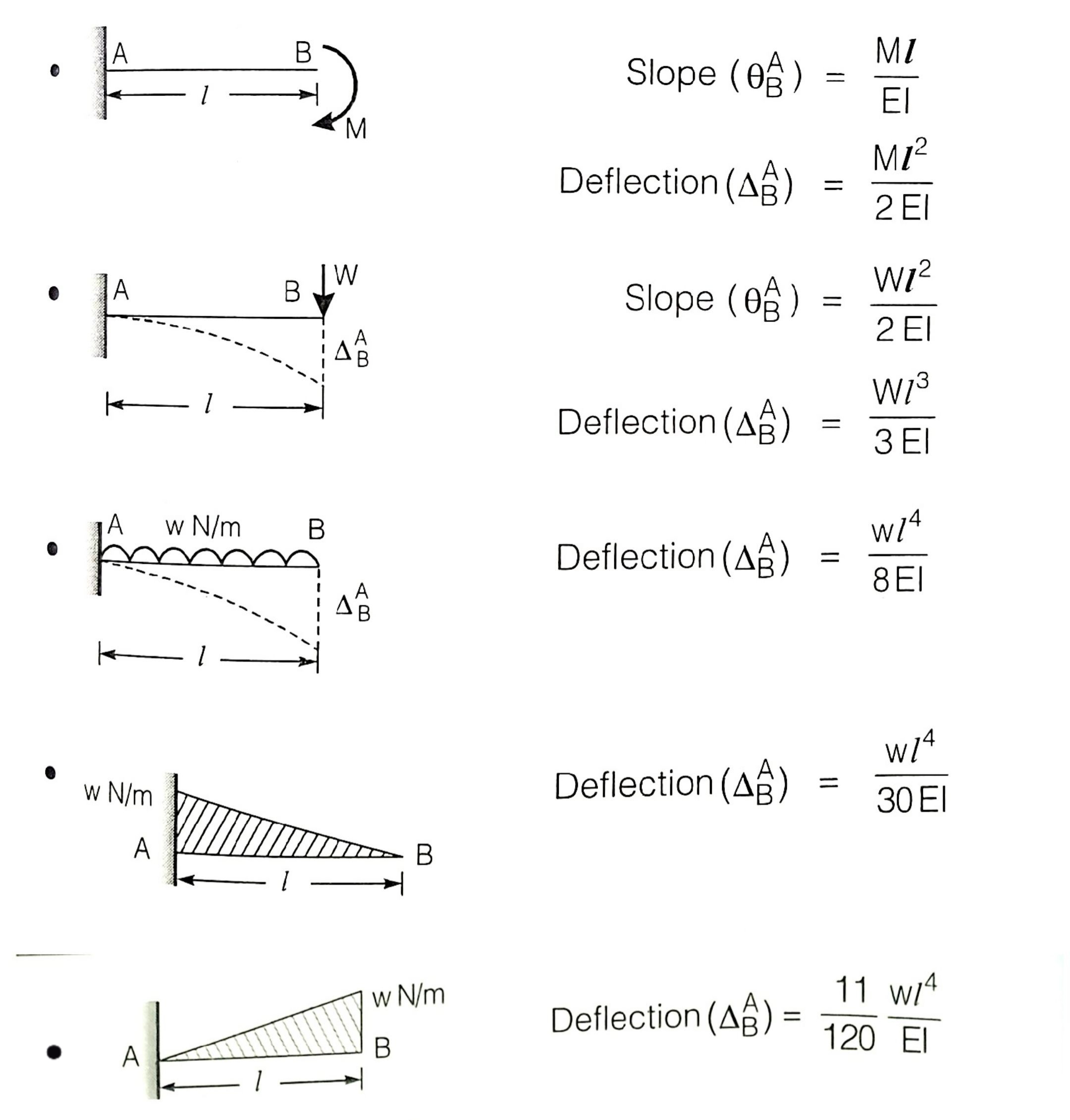
The slope of the beam at a point is the derivative of the deflection with respect to the length of the beam:
d2>y/dx2 = M(x) / (EI)
The deflection at a point can be calculated by integrating the slope function. For practical purposes, different methods can be used to determine these values:
- Double Integration Method: Integrate the differential equation twice to obtain deflection equations.
- Macaulay’s Method: A special integration method for calculating deflection and slope when dealing with multiple loads.
- Moment-Area Theorem (Mohr’s Theorems): Utilizes the area of the bending moment diagram to calculate deflections and slopes.
- Conjugate Beam Method: A method where a conjugate beam is used to find the deflection by solving the beam’s slope and deflection equations.
- Method of Superposition: Used for calculating deflection by combining the effects of different loads and supports.
3. Calculations of Deflection for Determinate Beams
Double Integration Method
This method involves integrating the differential equation twice. The process is:
- Determine the bending moment function
M(x)for the beam. - Integrate
d2>y/dx2 = M(x) / (EI)once to find the slope equation. - Integrate the slope equation to obtain the deflection equation.
- Apply boundary conditions to solve for constants of integration.
Macaulay’s Method
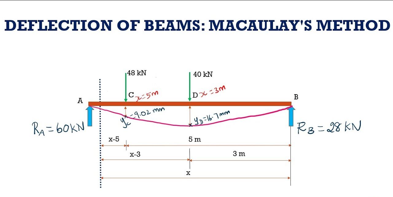
Macaulay’s method simplifies the integration process for beams with multiple loads and support conditions:
- Divide the beam into sections based on load and support locations.
- Write the bending moment equation for each section.
- Integrate the moment equation section by section to find the deflection and slope.
- Apply boundary conditions to determine constants of integration.
Theorem of Area-Moment Method (Mohr’s Theorems)
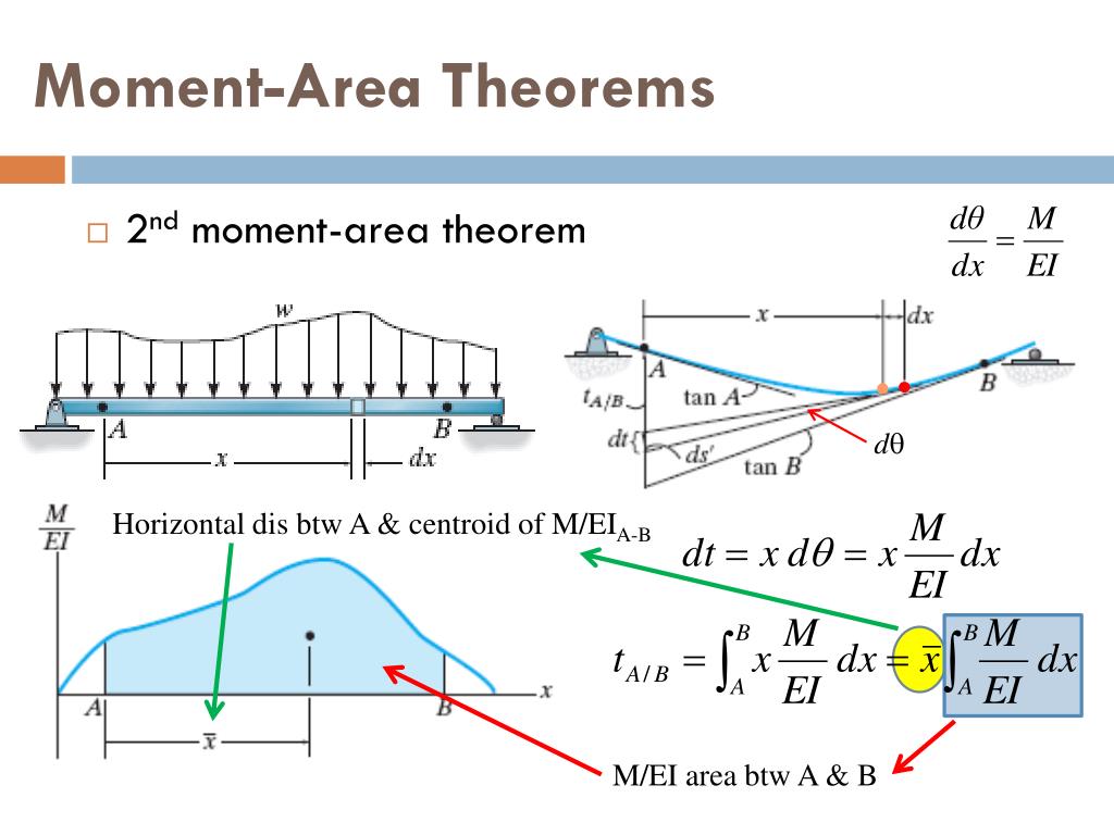
Mohr’s theorems involve the following steps:
- Construct the bending moment diagram (BMD).
- Calculate the area of the BMD to determine the change in slope.
- Calculate the first moment of the BMD area to determine deflection.
- Use the calculated values to find the deflection and slope at any point.
Moment Diagram by Parts
For complex beams, divide the beam into simpler parts, each with its own moment diagram:
- Determine the moment diagram for each part separately.
- Combine the moment diagrams to obtain the overall moment diagram.
4. Deflection of Cantilever Beams
For a cantilever beam with various loading conditions, the deflection can be calculated using the methods mentioned above. Common loading conditions include:
- Point Load at Free End: Maximum deflection occurs at the free end.
- Uniformly Distributed Load: The deflection is parabolic with maximum deflection at the free end.
5. Deflection in Simply Supported Beams
For simply supported beams:
- Point Load in the Middle: Maximum deflection occurs at the center.
- Uniformly Distributed Load: Maximum deflection is at the center, with a parabolic curve.
6. Mid-Span Deflection
The deflection at mid-span can be particularly important for design and analysis. For beams with a central load or uniform load, use the applicable equations to find mid-span deflection.
7. Conjugate Beam Method
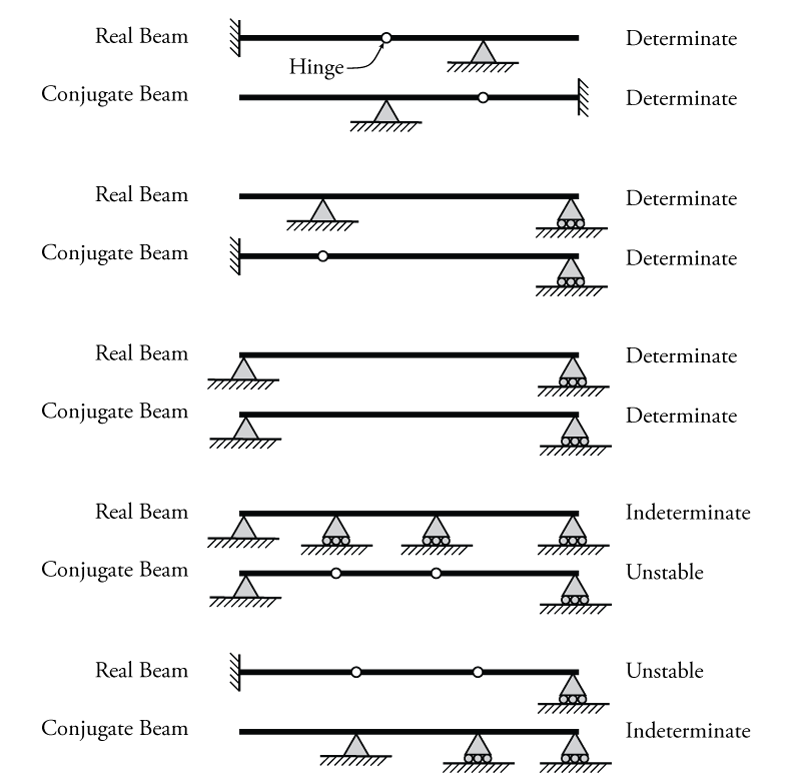
This method involves:
- Creating a conjugate beam with the same length but different support conditions.
- Calculating the slope and deflection using the conjugate beam’s moment diagram.
8. Method of Superposition
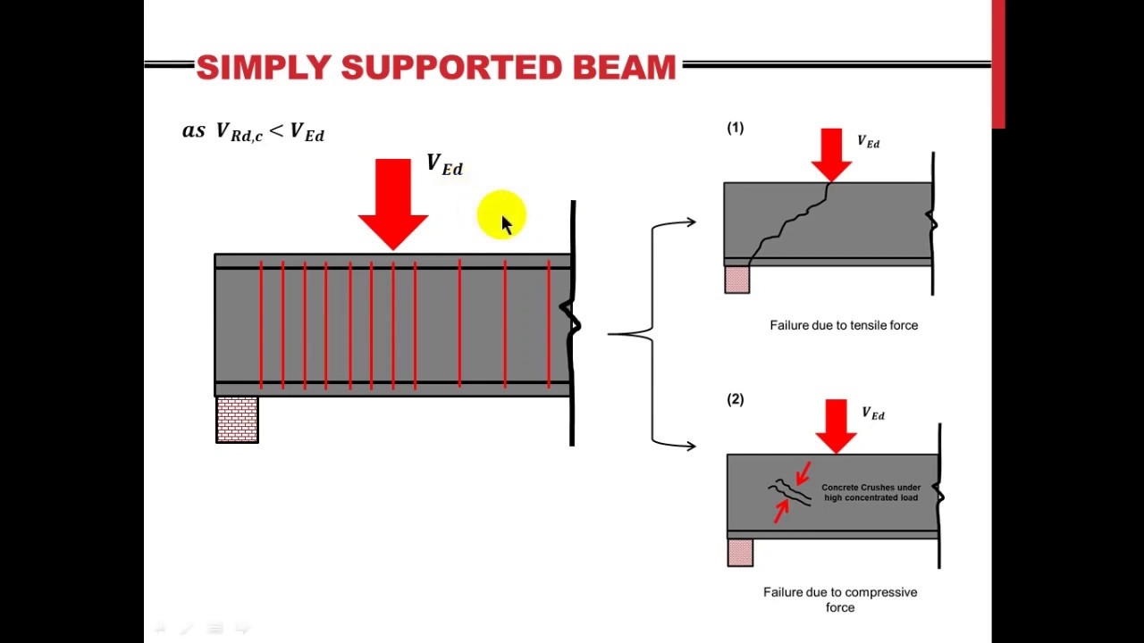
To calculate deflection using the method of superposition:
- Analyze the effect of each load separately.
- Combine the effects of all loads to determine the total deflection.
- Understanding the deflection of beams is crucial for structural analysis and design. Various methods, including double integration, Macaulay’s method, the moment-area method, and others, provide tools for analyzing and calculating deflections under different loading conditions.
Texts:
S. Ramamrutham, “Strength of Materials”, Dhanpat Rai and Sons, New Delhi.
F. L. Singer, Pytle, “Strength of Materials”, Harper Collins Publishers, 2002.
S. Timoshenko, “Strength of Materials: Part-I (Elementary Theory and Problems)”, CBS
Publishers, New Delhi.
References:
E. P.Popov, “Introduction to Mechanics of Solid”, Prentice Hall, 2nd edition, 2005.
S. H. Crandall, N. C. Dahl, T. J. Lardner, “An introduction to the Mechanics of Solids”, Tata
McGraw Hill Publications, 1978.
S. B. Punmia, “Mechanics of Structure”, Charotar Publishers, Anand.
