Metallurgy and Material Science
FUNDAMENTALS
Stucture of Materials
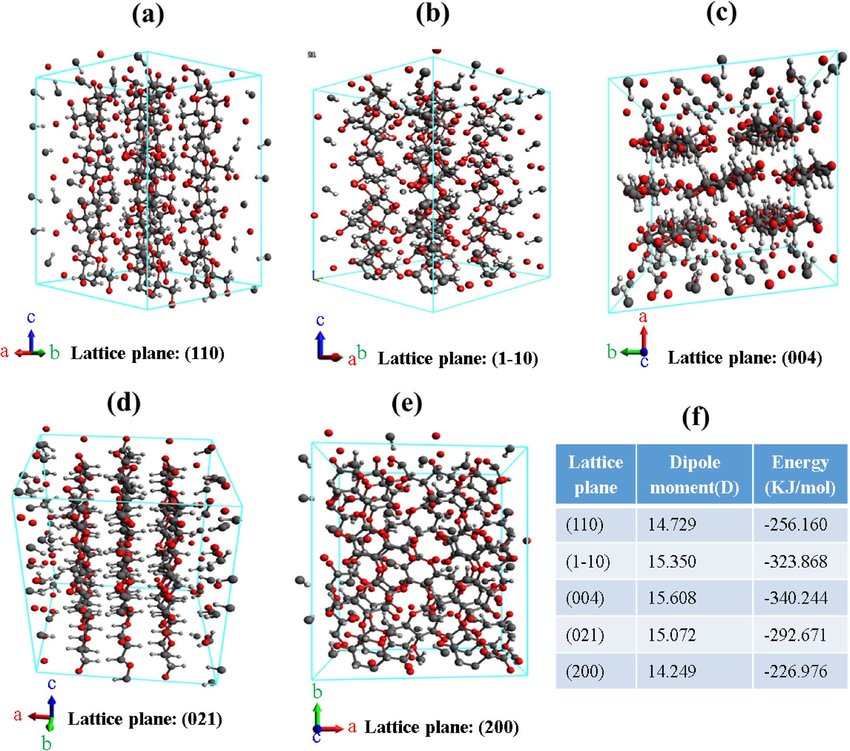
Crystal Structures
Materials can be categorized based on their internal arrangement of atoms. The repeating pattern in solid materials is called a crystal structure. The most common crystal structures in materials are:
- Face-Centered Cubic (FCC): Atoms are located at each corner and at the centers of all the faces of the cube. Examples: Aluminum, copper, and gold.
- Body-Centered Cubic (BCC): Atoms are located at each corner and at the center of the cube. Examples: Iron, chromium, and molybdenum.
- Hexagonal Close-Packed (HCP): Atoms are closely packed in a hexagonal lattice structure. Examples: Zinc, magnesium, and titanium.
Indexing of Lattice Planes
The orientation of planes in a crystal lattice is described using Miller indices. Miller indices are determined by taking the reciprocals of the intercepts that a plane makes with the crystallographic axes. The steps to find Miller indices are:
- Determine the intercepts of the plane on the crystallographic axes.
- Take the reciprocal of the intercepts.
- Clear any fractions to get whole numbers.
The Miller indices are represented as three integers in parentheses, such as (hkl), where \(h\), \(k\), and \(l\) are the reciprocals of the intercepts along the x, y, and z axes, respectively.
Imperfections in Crystals
Crystals are not always perfect. There are various types of imperfections or defects in crystals, which affect their properties:
Point Defects
- Vacancies: Missing atoms in a crystal lattice.
- Interstitial Defects: Extra atoms placed in the interstitial sites of a crystal.
- Substitutional Defects: Foreign atoms replace the host atoms in the crystal lattice.
Line Defects (Dislocations)
Dislocations are imperfections in the crystal lattice that occur along a line. These defects enable materials to deform plastically under stress:
- Edge Dislocation: Occurs when an extra half-plane of atoms is inserted into the crystal lattice.
- Screw Dislocation: A dislocation formed by the application of shear stress, causing a helical arrangement of atoms around the dislocation line.
Mechanism of Plastic Deformation
Plastic deformation occurs when a material is subjected to a stress greater than its yield strength. The mechanisms through which plastic deformation occurs in crystals include:
- Dislocation Motion: Dislocations move through the crystal lattice, allowing the material to deform under applied stress.
- Slip Systems: Slip occurs along specific crystallographic planes (called slip planes) and directions (called slip directions) that provide the least resistance to dislocation motion.
- Twining: Deformation caused by the reorientation of the crystal lattice along a specific plane, typically occurring at low temperatures or high strain rates.
Plastic Deformation of Polycrystalline Materials
In polycrystalline materials, the grains have different orientations, and plastic deformation occurs when dislocations move through individual grains. However, the deformation is constrained by grain boundaries, which can hinder dislocation motion. This results in:
- Strain Hardening: The material becomes stronger as dislocations accumulate during deformation.
- Grain Boundary Strengthening: Smaller grain sizes increase the strength of materials, as grain boundaries block dislocation motion.
Unit 2: Equilibrium Diagrams
Definitions of Terms
In materials science, several terms are important to understand when discussing equilibrium diagrams:
- Phase: A region of material that is physically and chemically homogeneous.
- Component: The elements or compounds that are present in the system (e.g., iron, carbon).
- Solubility Limit: The maximum amount of one substance that can dissolve in another at a given temperature and pressure.
- Alloy: A mixture of two or more elements, where at least one is a metal.
- Solid Solution: A single-phase alloy where atoms of the solute occupy positions within the crystal lattice of the solvent.
Rules of Solid-Solubility
Solid solubility refers to the extent to which a solute can dissolve into a solvent to form a solid solution. The Hume-Rothery rules are guidelines to predict the solubility of two metals in each other:
- The atomic radii of the two elements must differ by less than 15%.
- The elements must have the same crystal structure.
- They must have similar electronegativities.
- They must have the same valence.
Gibb’s Phase Rule
Gibb’s Phase Rule is a formula used to determine the number of degrees of freedom (F) in a system:
F = C – P + 2
Where:
- C: Number of components.
- P: Number of phases present.
The phase rule helps in analyzing the behavior of multi-phase systems, such as alloys in different phases.
Solidification of a Pure Metal
The solidification process involves the transformation from liquid to solid. As a pure metal cools, it begins to crystallize at a specific temperature, known as the melting point. During solidification, latent heat is released, and nucleation occurs, followed by the growth of crystals.
Plotting of Equilibrium Diagrams
Equilibrium diagrams (phase diagrams) are graphical representations that show the relationship between temperature, composition, and phases present at equilibrium. These diagrams are useful for understanding alloy systems and predicting phase changes during heating and cooling.
Lever Rule
The lever rule is a tool used to determine the proportions of phases in a two-phase region of a binary phase diagram. It is expressed as:
wL = (frac{C_s – C_0}{C_s – C_L})
Where:
- wL: Weight fraction of the liquid phase.
- Cs: Composition of the solid phase.
- CL: Composition of the liquid phase.
- C0: Overall composition of the alloy.

Iron-Carbon (Fe-C) Equilibrium Diagram
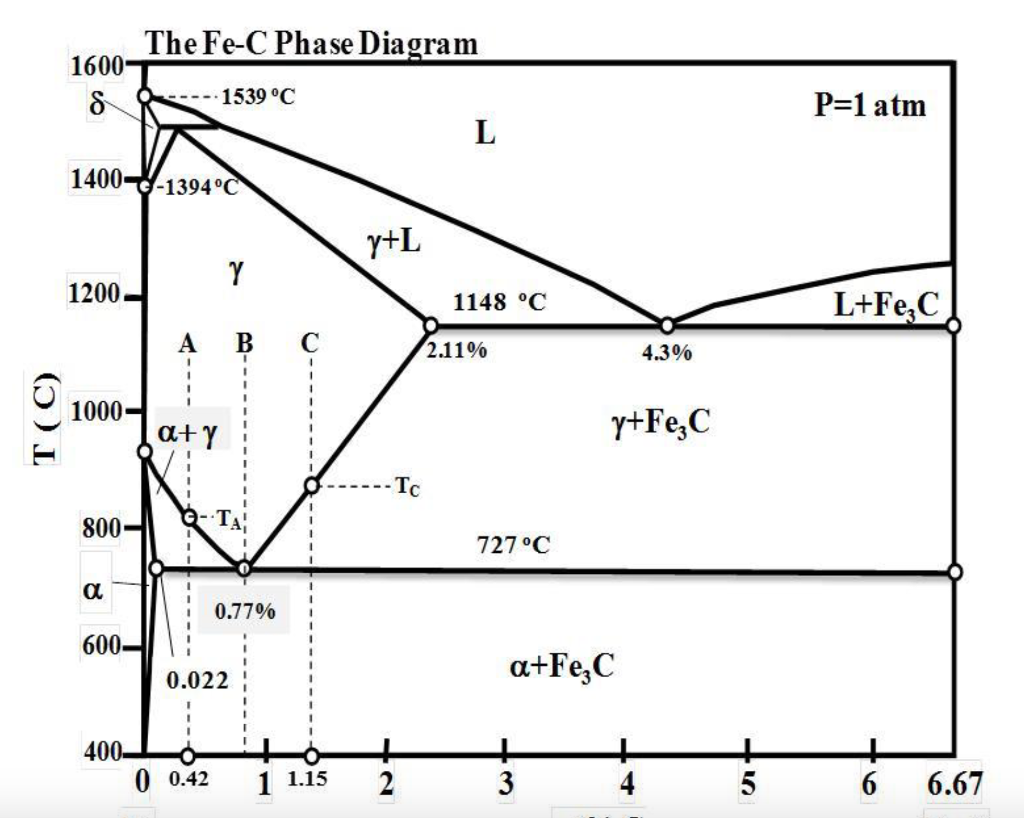
The Iron-Carbon equilibrium diagram is one of the most important phase diagrams for understanding the behavior of steels. It shows the phases present in the Fe-C system at different temperatures and compositions. Important features of this diagram include:
- Austenite (γ-Fe): A phase with a face-centered cubic (FCC) structure, stable at higher temperatures.
- Ferrite (α-Fe): A phase with a body-centered cubic (BCC) structure, stable at lower temperatures.
- Cementite (Fe3C): A hard and brittle intermetallic compound.
Critical Temperatures
The critical temperatures in the Fe-C phase diagram include:
- A1: 723°C, where austenite transforms to ferrite and cementite.
- A3: The temperature above which austenite forms from ferrite.
- Acm: The temperature where austenite transforms to cementite.
Solidification and Microstructure of Slowly Cooled Steels
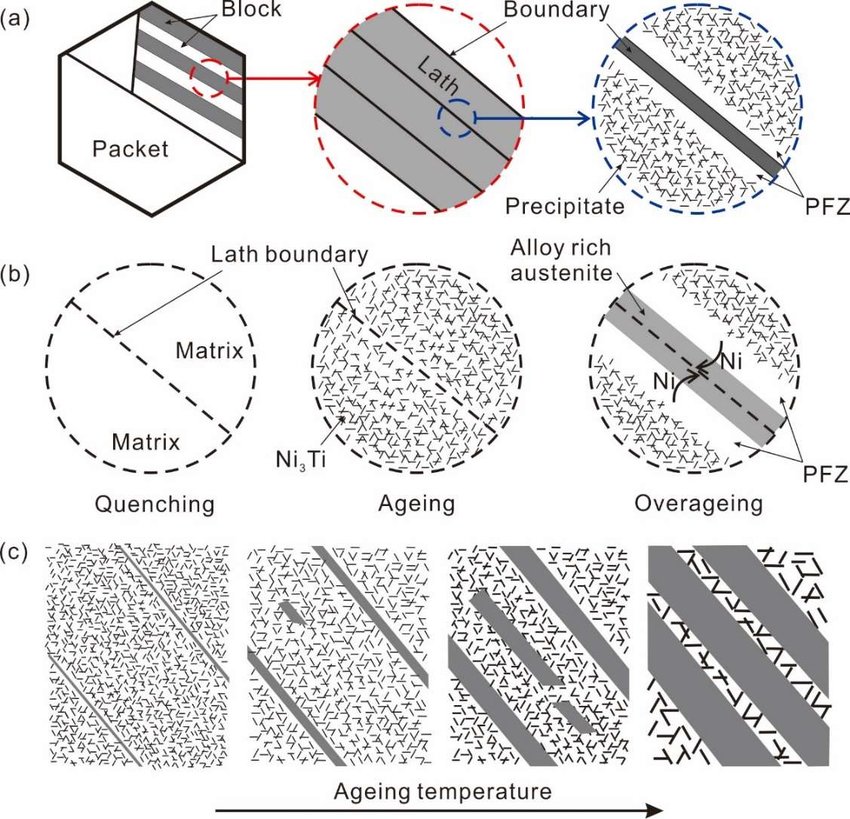
As steel is slowly cooled, it passes through several transformations. For example, austenite transforms into pearlite, a mixture of ferrite and cementite. The resulting microstructure consists of alternating layers of ferrite and cementite, giving steel its characteristic properties.
Non-Equilibrium Cooling of Steels
During non-equilibrium cooling, the phases formed are different from those predicted by the equilibrium diagram. This is due to rapid cooling rates that prevent the phases from reaching equilibrium. This often results in the formation of martensite, a hard and brittle phase.
Classification and Application of Steels
Steels are classified based on their carbon content and alloying elements:
- Low-carbon steel: Used for structural applications due to its ductility and toughness.
- Medium-carbon steel: Used in automotive components and machinery parts for better strength and hardness.
- High-carbon steel: Used in tools and cutting instruments due to its hardness.
Specification of Steels
Steels are specified by standards such as ASTM and ISO. These specifications define the chemical composition, mechanical properties, and intended applications of different types of steel. For example, AISI 1045 refers to medium-carbon steel with 0.45% carbon.
TTT Diagram (Time-Temperature-Transformation)
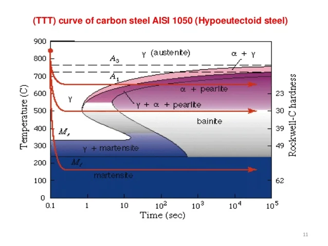
The TTT diagram represents the isothermal transformation of austenite into other phases over time. It shows the critical time and temperature for the formation of pearlite, bainite, and martensite. Rapid cooling results in martensite, while slow cooling produces pearlite.
Critical Cooling Rate
The critical cooling rate is the minimum rate at which austenite must be cooled to avoid the formation of pearlite or bainite and obtain martensite. The faster the cooling rate, the harder and more brittle the steel will be.
CCT Diagram (Continuous Cooling Transformation)
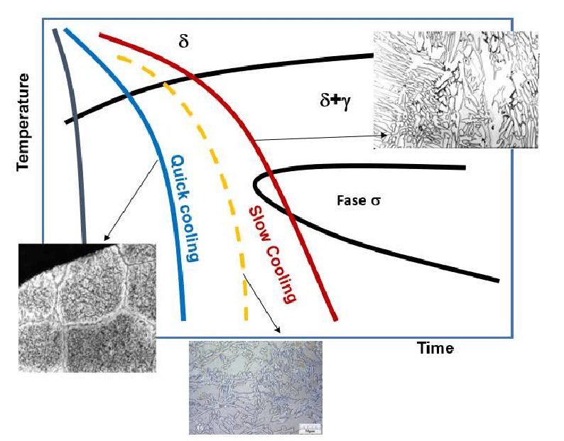
The CCT diagram shows the transformation of austenite during continuous cooling. Unlike the TTT diagram, which is for isothermal transformations, the CCT diagram takes into account the gradual cooling process that occurs in practical situations, such as quenching.
Unit 3: Heat Treatment
Heat treatment is a controlled process used to alter the physical (and sometimes chemical) properties of materials, especially metals. It involves heating and cooling materials in a regulated manner to achieve desired characteristics such as hardness, toughness, ductility, and strength.
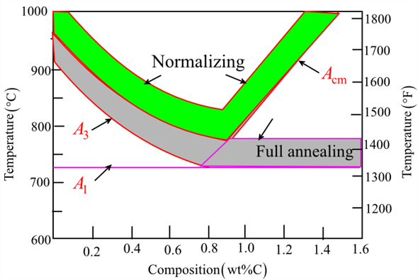
1. Heat Treatment of Steels
Steels are one of the most common materials subjected to heat treatment. By controlling the heating and cooling process, various mechanical properties of steel can be enhanced or modified.
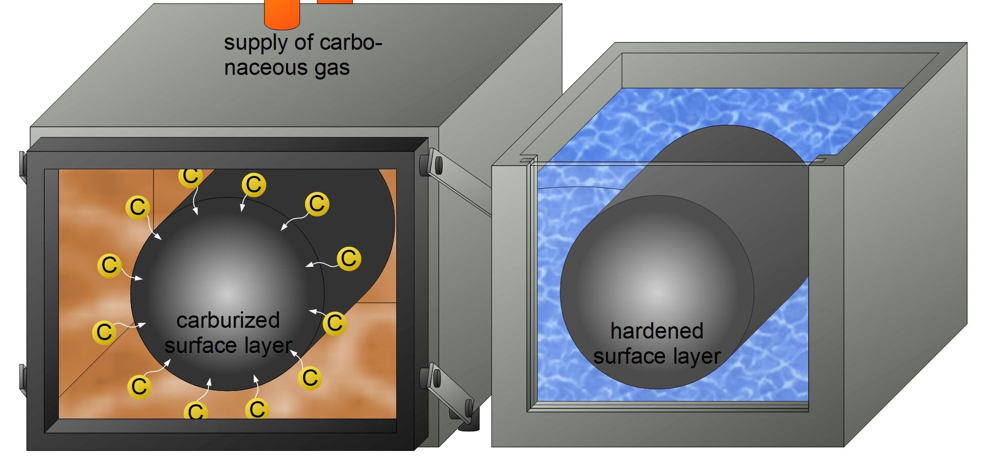
Key Heat Treatment Processes:
- Annealing: A process that involves heating the steel to a specific temperature and then allowing it to cool slowly. This softens the material, improves ductility, and relieves internal stresses.
- Normalizing: The steel is heated above its critical temperature and then allowed to air cool. This process refines the grain structure and improves the toughness and strength of the steel.
- Hardening: The steel is heated to a high temperature and then rapidly cooled (quenched). This increases the hardness and strength of the steel by transforming its microstructure to martensite.
- Tempering: After hardening, steel may be too brittle. Tempering involves reheating the hardened steel to a lower temperature and then cooling it slowly. This reduces brittleness while maintaining a degree of hardness and strength.
2. Cooling Media
The medium used for cooling (quenching) in heat treatment significantly affects the properties of the material. Common cooling media include:
- Air: Used in normalizing processes for gradual cooling.
- Water: Provides rapid cooling but may introduce internal stresses or cracking due to uneven cooling rates.
- Oil: Provides slower cooling than water, reducing the risk of cracking but still allowing significant hardening.
- Brine (saltwater): Produces more rapid cooling than water and is used in certain hardening processes.
3. Quenching and Hardenability
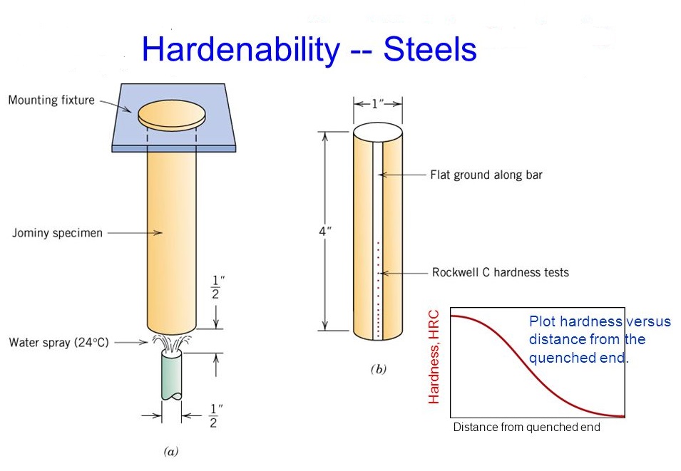
Quenching is the process of rapidly cooling heated steel to lock in the microstructure changes (like forming martensite), thereby increasing hardness. Different quenching media (water, oil, air) are used to control the rate of cooling and prevent issues such as warping or cracking.
Hardenability refers to the ability of a steel alloy to be hardened by forming martensite when quenched. It depends on the composition of the steel and is measured by the depth and distribution of hardness induced by quenching.
4. Surface Hardening Processes
Surface hardening, or case hardening, refers to techniques that harden the surface of a material while keeping its core softer, providing a combination of wear resistance and toughness.
Common Surface Hardening Techniques:
- Nitriding: A process in which nitrogen is diffused into the surface of the steel at a high temperature to form a hard, wear-resistant surface layer. This method does not require quenching and is typically performed in an ammonia gas environment.
- Carbo-nitriding: Similar to nitriding, but carbon is also introduced along with nitrogen to improve surface hardness. It’s used for components that need both surface hardness and improved wear resistance.
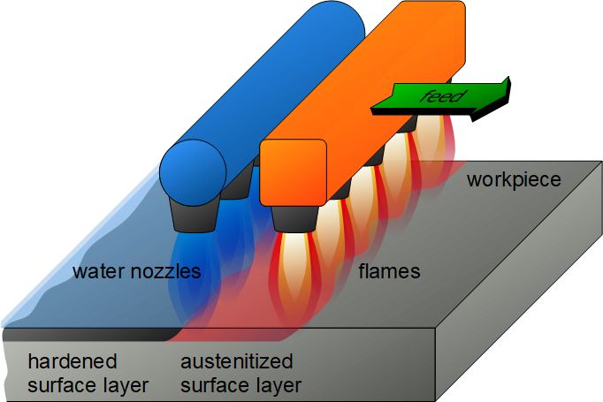
- Flame Hardening: Involves heating the surface of the steel using an oxy-acetylene flame and then rapidly quenching it. This process is often used for large components where selective hardening is needed.
- Induction Hardening: A non-contact process where a high-frequency alternating current is used to induce heat in the surface layer of the steel, followed by rapid cooling (quenching). Induction hardening is highly controllable and used for precision applications.
Unit 4: Metallography
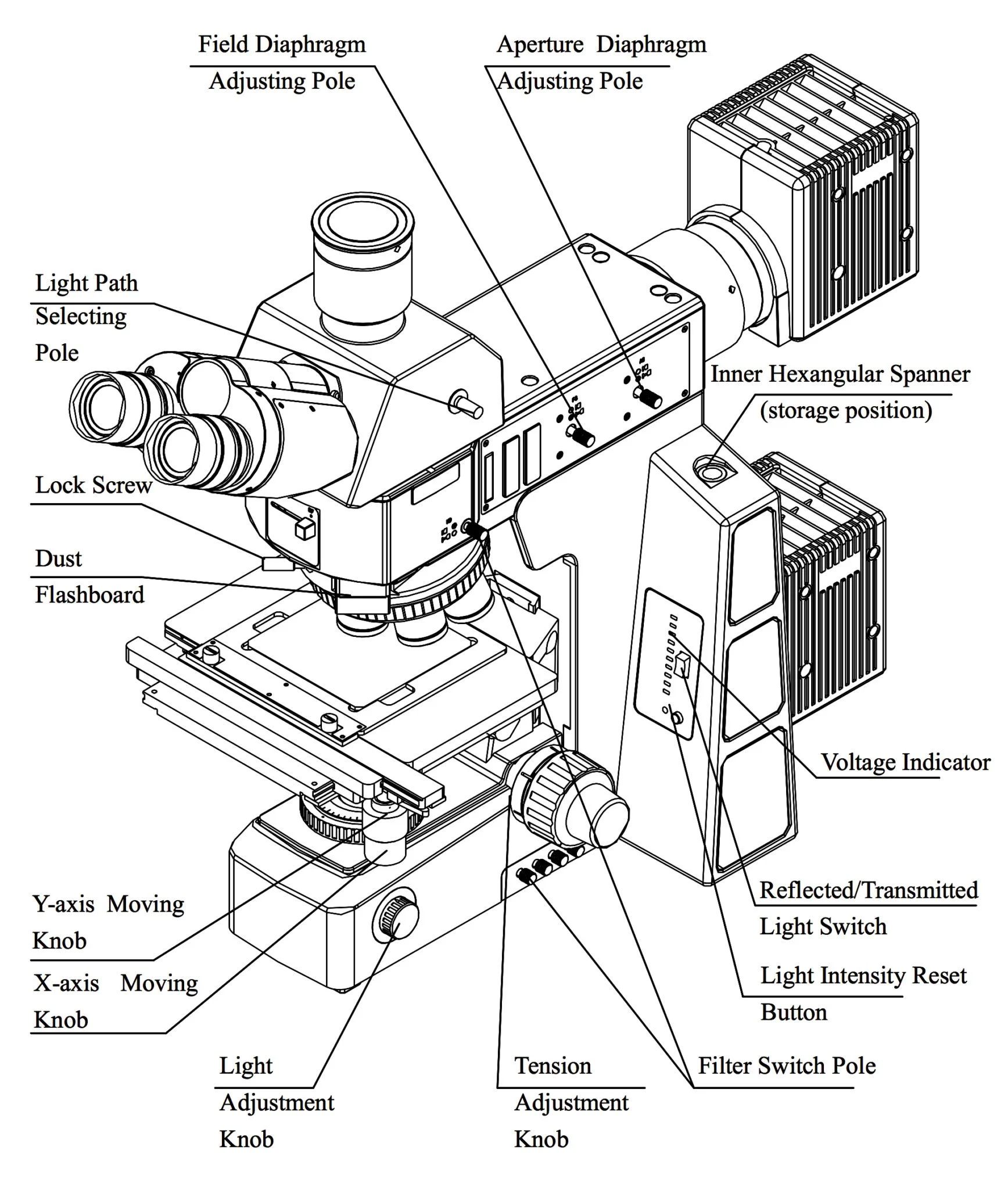
Metallography is the study of the microstructure of metals and alloys using various microscopic techniques. The goal is to reveal the structure and composition of materials to assess their properties, quality, and performance. Metallographic analysis is critical in failure analysis, quality control, and research in materials science.
1. Microscopy
Microscopy is a fundamental technique used in metallography to observe and study the structure of metals at magnifications ranging from 50x to 2000x. The most commonly used microscopes include:
- Optical Microscopes: These microscopes use visible light and optical lenses to magnify the microstructure of polished and etched specimens.
- Electron Microscopes: These microscopes use a beam of electrons to create highly magnified images of metal surfaces, providing greater detail and resolution than optical microscopes. Types of electron microscopes include the Scanning Electron Microscope (SEM) and Transmission Electron Microscope (TEM).
2. Specimen Preparation
The preparation of a metallographic specimen is essential for obtaining accurate and consistent results during microscopic examination. The following steps are involved in specimen preparation:
2.1 Cutting
The metal sample is cut from the bulk material using a precision saw or other suitable methods. The cutting process should be done carefully to avoid introducing artifacts like deformation or cracking.
2.2 Mounting
The specimen is mounted in a resin or plastic holder to make it easier to handle during polishing and examination. There are two common methods for mounting:
- Cold Mounting: The specimen is embedded in a polymer resin that cures at room temperature.
- Hot Mounting: The specimen is placed in a heated mold with thermosetting resin under pressure to form a hard mount.
2.3 Grinding
Grinding is the process of removing excess material and irregularities from the surface of the specimen. This is done using abrasive papers of progressively finer grits, typically starting from coarse grits (e.g., 220 grit) and gradually moving to finer grits (e.g., 1200 grit) to achieve a smooth surface.
3. Polishing
Polishing is a critical step in specimen preparation that removes surface scratches introduced during grinding and produces a smooth, mirror-like surface for microscopic examination. Polishing is typically done using polishing abrasives and cloths. The most common polishing abrasives include:
- Alumina (Al2O3): Fine particles of aluminum oxide used for final polishing stages.
- Diamond Paste: Diamond particles suspended in a paste are used for high-quality polishing and creating ultra-smooth surfaces.
- Silicon Carbide (SiC): Used for rough polishing before final finishing with finer abrasives.
Polishing cloths are also used in conjunction with polishing abrasives to further smooth the specimen surface. Different types of cloths are selected based on the material being polished and the desired finish.
3.1 Electrolytic Polishing
Electrolytic polishing is an alternative method where the specimen is polished using an electrolytic cell. The specimen is made the anode in an electrolytic bath, and the current removes surface material selectively, creating a smooth finish. This method is used for hard-to-polish materials and provides a strain-free surface.
4. Etching Procedure and Reagents
Etching is the process of chemically treating the polished specimen to reveal its microstructure. Etching reagents attack different phases of the material, providing contrast between grain boundaries, phases, and inclusions.
- Nital: A mixture of nitric acid and ethanol commonly used to etch steels and reveal ferrite and pearlite grains.
- Keller’s Reagent: Used for etching aluminum alloys.
- Picro-Sirius: A reagent used to reveal the cementite phase in carbon steels.
4.1 Electrolytic Etching
In electrolytic etching, the specimen is subjected to an electric current in an etching solution. This technique is often used when chemical etching cannot adequately reveal the microstructure or when a higher degree of control over the etching process is required.
5. Optical Metallurgical Microscope
An optical metallurgical microscope is the primary tool used to examine the microstructure of prepared metallographic specimens. It uses light and a series of optical lenses to magnify the surface features of the specimen. The microstructural features that can be observed include:
- Grain boundaries
- Inclusions and impurities
- Phases and phase distributions
- Surface defects such as cracks or voids
6. Sulphur Printing
Sulphur printing is a technique used to detect the presence and distribution of sulfur in steels. Sulfur, often present as sulfide inclusions, can affect the properties of steel and lead to undesirable characteristics such as brittleness. Sulfur printing makes these inclusions visible, allowing for quality control and analysis.
7. Flow Line Observations
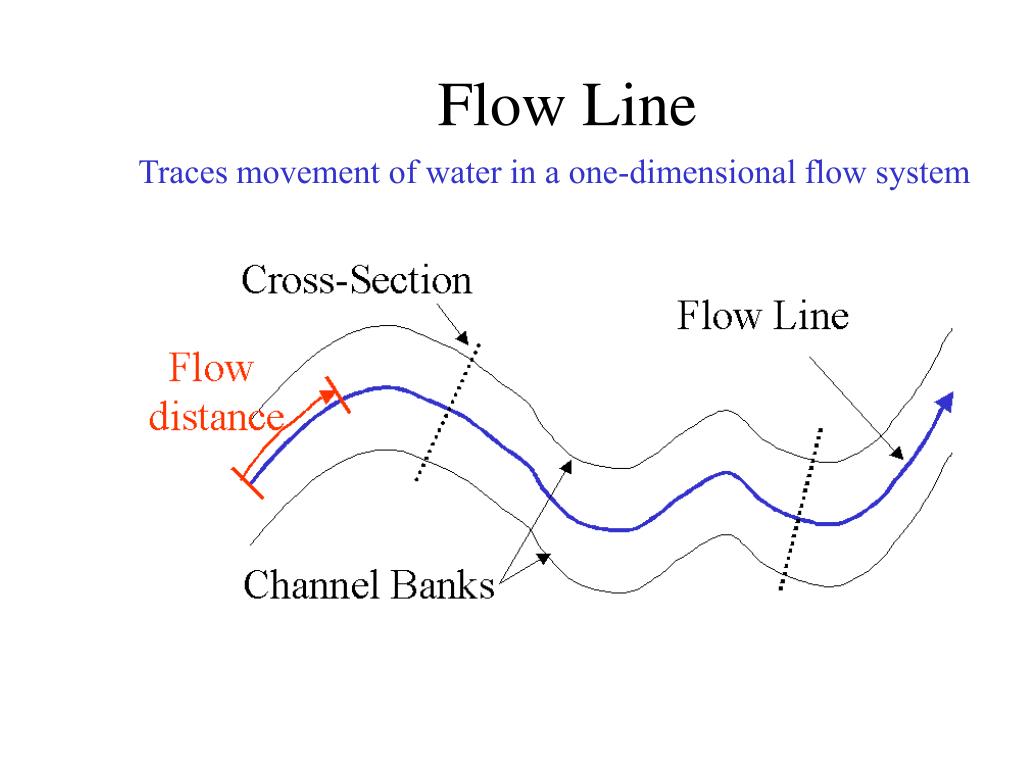
Flow lines are patterns formed by the movement of grains and phases during the deformation of metals. These can be observed in forged or cast materials and help in understanding the material’s history of processing and deformation.
8. Examination of Fractures
The examination of fractures is an essential aspect of failure analysis in metallography. Fracture surfaces can provide information about the mode of failure, such as ductile fracture, brittle fracture, fatigue, or stress corrosion cracking. Microscopic and macroscopic features are analyzed to determine the root cause of failure.
9. Spark Test
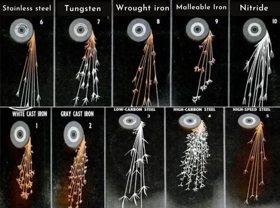
The spark test is a quick and inexpensive method used to identify different types of steels. In this test, a metal sample is ground against a high-speed abrasive wheel, producing sparks. The color, shape, and length of the sparks can provide clues about the material’s composition, particularly the carbon content.
10. Electron Microscope
The electron microscope is a powerful tool for observing extremely fine details of the microstructure at very high magnifications. Unlike optical microscopes, electron microscopes use a beam of electrons instead of light. There are two main types:
- Scanning Electron Microscope (SEM): Provides a detailed, three-dimensional image of the surface by scanning it with a focused beam of electrons.
- Transmission Electron Microscope (TEM): Provides high-resolution images of the internal structure of thin samples by transmitting electrons through the specimen.

Unit 5: Strengthening Mechanisms and Non-destructive Testing
Strengthening Mechanisms
1. Refinement of Grain Size
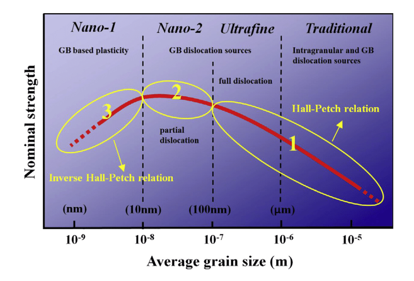
Grain size refinement is a method of strengthening materials by reducing the size of grains in the microstructure.
Hall-Petch relationship:
Smaller grains mean more grain boundaries, which impede dislocation movement, thus increasing the material’s strength.
Formula:
σy = σ0 + k / √d
Where:
- σy is the yield stress.
- σ0 is a material constant for the starting stress.
- k is a strengthening coefficient.
- d is the average grain diameter.
2. Cold Working / Strain Hardening
When metals are deformed plastically at temperatures lower than their recrystallization point, they become stronger and harder through dislocation density increase. Dislocations accumulate, making further movement more difficult, thus hardening the material.
Formula:
σ = Kεn
Where:
- σ is the true stress.
- ε is the true strain.
- K is the strength coefficient.
- n is the strain-hardening exponent.
3. Solid Solution Strengthening
Adding impurity atoms to a pure metal to form a solid solution increases its strength. The foreign atoms either substitute host atoms or fit into interstitial sites, distorting the lattice and impeding dislocation motion.
4. Dispersion Strengthening
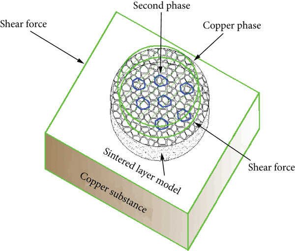
Involves dispersing fine, hard particles (like oxides or carbides) within the metal matrix to block dislocation movement. These particles are generally stable at high temperatures, making the material resistant to softening during service.
5. Precipitation Hardening (Age Hardening)
This process involves forming fine precipitates in the metal matrix, which hinder dislocation motion and strengthen the material.
Steps:
- Solution Treatment: Dissolve alloying elements at high temperatures.
- Quenching: Rapid cooling to form a supersaturated solution.
- Aging: Reheating to allow small precipitates to form.
Non-destructive Testing (NDT)
1. Magnetic Particle Inspection (MPI)
Detects surface and slightly subsurface defects in ferromagnetic materials. The material is magnetized, and iron particles are sprinkled over the surface. Defects disrupt the magnetic field, causing particles to cluster, making the defects visible.
2. Dye Penetrant Inspection (DPI)
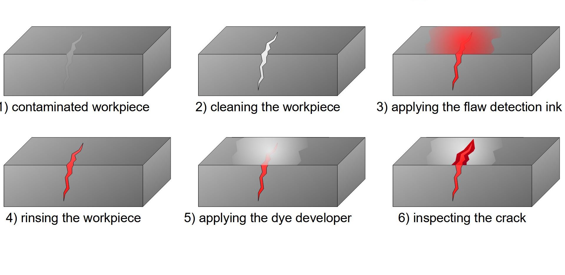
Used to detect surface cracks and defects on non-porous materials. The surface is cleaned, a penetrant dye is applied, and after a waiting period, the excess dye is removed, and a developer is applied to draw out the dye from defects, making them visible under UV light.
3. Ultrasonic Inspection
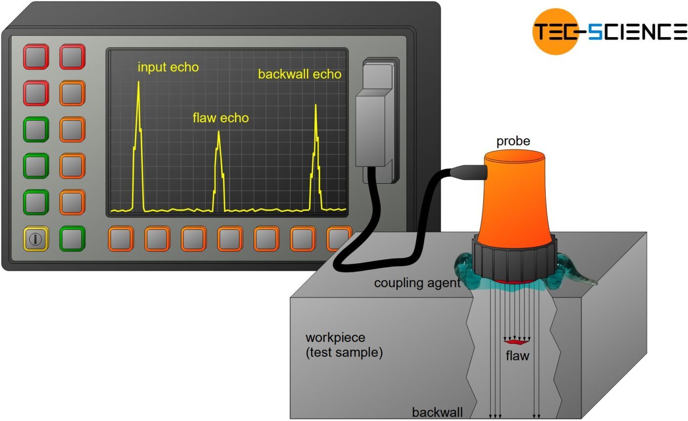
Uses high-frequency sound waves to detect internal defects in materials. Sound waves reflect when they encounter a flaw, and the transducer measures the time to detect the size and location of the defect.
4. Radiography (X-ray or Gamma Ray Inspection)
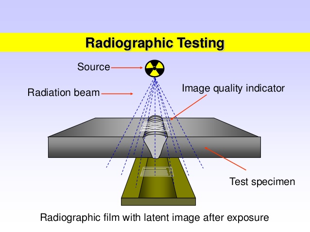
Uses X-rays or gamma rays to penetrate materials and reveal internal flaws. The radiation passes through the material and is captured on film or digital sensors, with defects appearing as dark or light areas on the image.
5. Eddy Current Testing
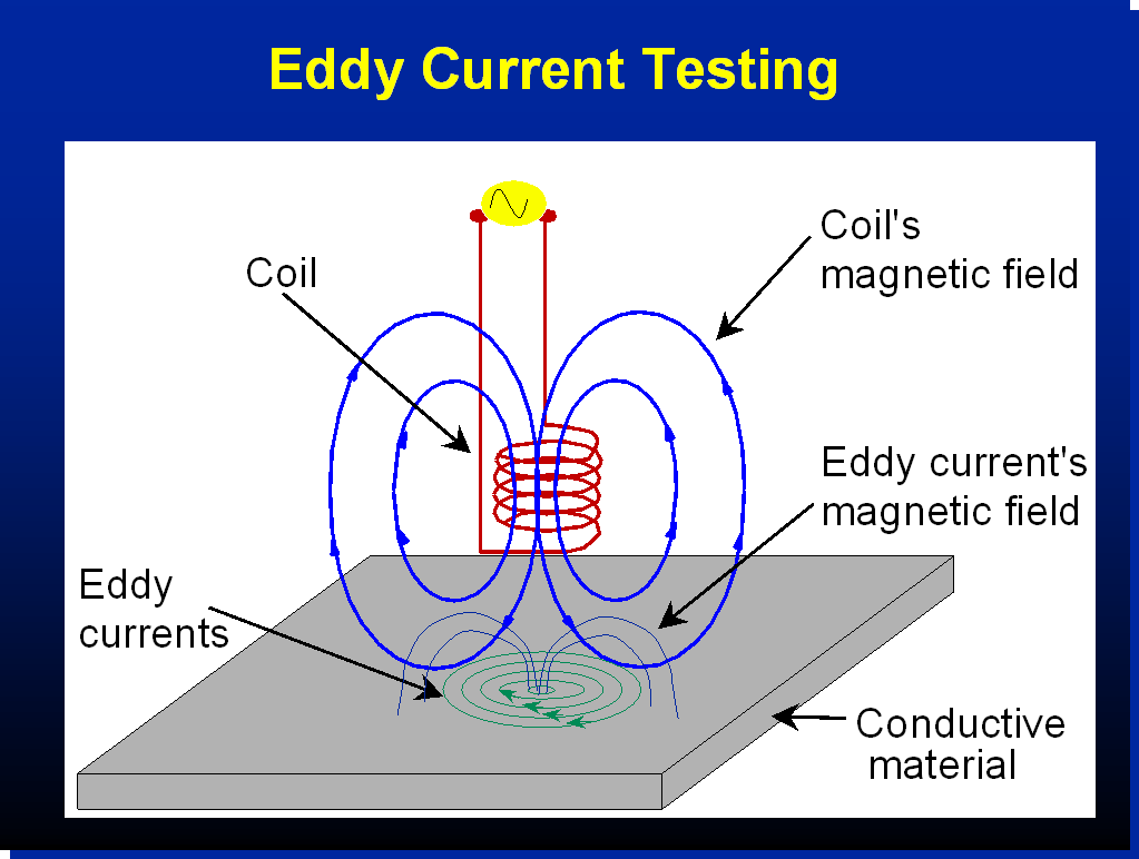
Used primarily for detecting surface and near-surface defects in conductive materials. An alternating current is passed through a coil, generating an electromagnetic field. Disruptions in eddy currents indicate the presence of defects.
Texts Books:
1. V. D. Kodgire, S.V. Kodgire, “Material Science and Metallurgy for Engineers”,
Everest Publishing House, Pune, 24thedition, 2008.
2. W. D. Callister, “Materials Science and Engineering: An Introduction”, John Wiley
andSons, 5
thedition,2001.
3. V. Raghvan, “Material Science Engineering”,
References:
1. V. B. John, “Introduction to Engineering Materials”, ELBS, 6thedition, 2001.
2. G. F. Carter, D. E. Paul, “ Materials Science and Engineering”, ASM International,
3rdedition, 2000.
3. T. E. Reed-Hill, R. Abbaschian, “Physical Metallurgy Principles”, Thomson, 3rdedition.
Prentice Hall of India Ltd., 1992.
