Manufacturing Process:02
Unit 1: Abrasive Machining and Finishing Operations
1. Introduction to Abrasive Machining
Abrasive machining is a material removal process that relies on the action of hard, sharp abrasive particles. This process is primarily used to achieve tight tolerances and good surface finish in a wide range of materials. Abrasive machining operations include processes like grinding, honing, lapping, and polishing, all of which involve the controlled removal of small amounts of material from the surface of the workpiece.
Abrasive machining is widely used in industries like automotive, aerospace, and precision engineering due to its ability to machine hard materials and achieve very fine surface finishes.
2. Abrasives and Bonded Abrasives
2.1 Grinding Wheels
Grinding wheels are essential components in abrasive machining processes. They consist of abrasive grains that are bonded together by a binding material. The selection of the appropriate grinding wheel depends on the material being machined, the required surface finish, and the specific grinding operation.
2.2 Bond Types
Grinding wheels are classified based on the type of bond used to hold the abrasive particles together:
- Vitrified Bond: Made from ceramic materials, vitrified bonds are strong and rigid, suitable for precision grinding. However, they are brittle and prone to breakage.
- Resinoid Bond: These bonds are made from synthetic resins. They are more flexible than vitrified bonds and can withstand higher grinding speeds.
- Metal Bond: Metal bonds are used for grinding hard materials like ceramics and glass. They offer high strength but are difficult to dress and shape.
2.3 Wheel Grade and Structure
The grade of a grinding wheel refers to the bond strength that holds the abrasive grains together. The structure refers to the spacing between the abrasive grains. A wheel’s grade and structure affect its cutting action, with harder wheels used for harder materials and softer wheels for softer materials.
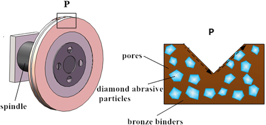
Diagram: Grinding Wheel Structure
3. Grinding Process
3.1 Grinding-Wheel Wear
Grinding wheels undergo wear during operation. There are three primary types of grinding wheel wear:
- Abrasive Wear: This occurs when abrasive grains become dull and fracture, resulting in a reduction in the wheel’s cutting ability.
- Attritious Wear: Attritious wear is caused by micro-fracturing of the abrasive grains due to the constant pressure and heat during grinding.
- Bond Fracture: In this case, the bond holding the abrasive grains weakens, leading to the grains falling out of the wheel.
3.2 Grinding Ratio
The grinding ratio is the ratio of the volume of material removed to the volume of wheel wear. It is expressed as:
3.3 Dressing, Truing, and Shaping of Grinding Wheels
Dressing: Dressing is the process of cleaning and reshaping the surface of the grinding wheel to restore its cutting ability.
Truing: Truing ensures that the grinding wheel is perfectly round and concentric with its axis of rotation. It helps in eliminating wheel imbalances.
Shaping: Shaping involves forming the grinding wheel into a specific profile to achieve the desired geometry on the workpiece.
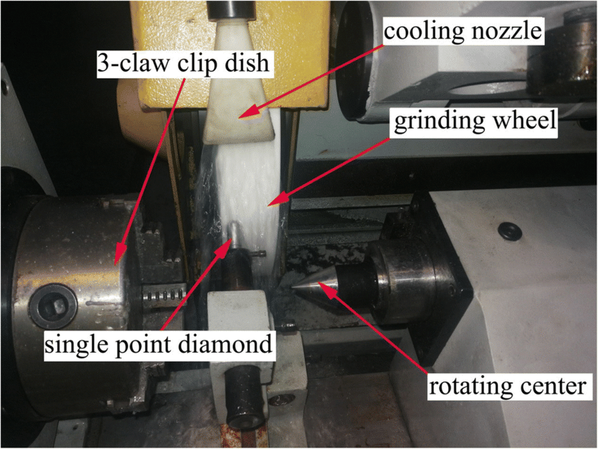
Diagram: Dressing a Grinding Wheel
3.4 Grindability of Materials and Wheel Selection
The grindability of a material refers to how easily it can be machined using an abrasive process. It depends on factors such as hardness, toughness, and thermal conductivity of the material.
When selecting a grinding wheel, factors such as wheel material, grain size, bond type, and grade must be considered based on the grindability of the workpiece material.
4. Grinding Operations and Machines
4.1 Types of Grinding Operations
Grinding operations can be broadly classified into the following types:
- Surface Grinding: The grinding wheel removes material from the surface of the workpiece. It is used to create flat surfaces and achieve high precision.
- Cylindrical Grinding: Used to machine cylindrical workpieces. The workpiece rotates around its axis as the grinding wheel cuts material.
- Centerless Grinding: In this operation, the workpiece is supported between two wheels—one grinding wheel and one regulating wheel—and material is removed as it rotates.
- Internal Grinding: Used to machine internal surfaces such as bores and holes.
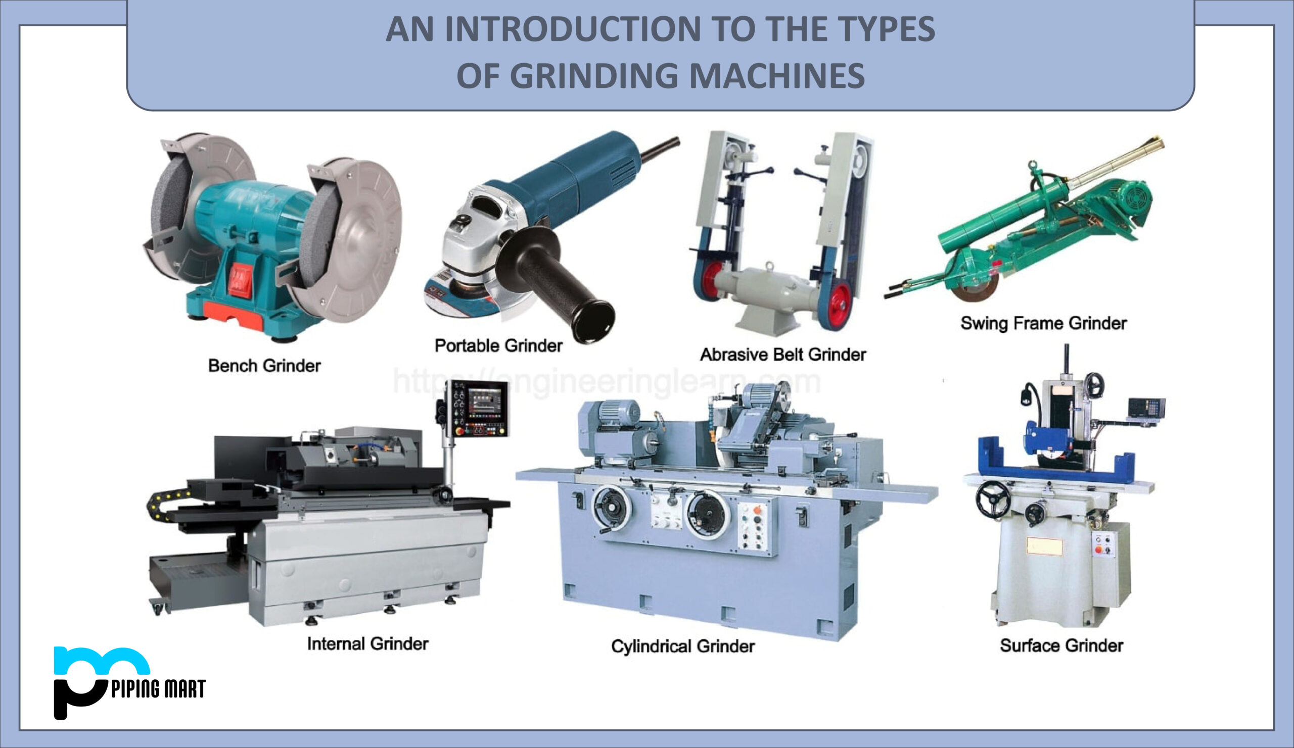
Diagram: Types of Grinding Machines
4.2 Finishing Operations
Finishing operations involve the use of fine abrasives to produce a high-quality surface finish. Common finishing processes include:
- Honing: Used for precision bore finishing. The honing tool consists of abrasive stones mounted on a mandrel that rotates and reciprocates inside the bore.
- Lapping: In lapping, a mixture of abrasive particles and a fluid is used to produce very smooth surfaces. The workpiece is rubbed against a lapping plate or another surface.
- Polishing: A polishing wheel, usually coated with a fine abrasive compound, is used to create a mirror-like finish on the workpiece.
Unit 2: Mechanics of Metal Cutting
1. Geometry of Single Point Cutting Tools
The geometry of a single-point cutting tool is essential for understanding how metal is removed during machining. The shape, angles, and orientation of the tool affect cutting efficiency, tool life, and surface finish. Single-point cutting tools are commonly used in operations like turning, shaping, and planning.
1.1 Terms and Definitions
- Cutting Edge: The part of the tool that is in direct contact with the workpiece during machining.
- Rake Angle (α): The angle between the rake face and the cutting direction. It influences chip flow and cutting forces.
- Clearance Angle (γ): The angle between the clearance face and the workpiece surface. It prevents the tool from rubbing against the material.
- Relief Angle: The angle between the flank and the surface being machined, allowing tool clearance.
- Nose Radius: The rounded tip of the tool that improves surface finish and tool life.
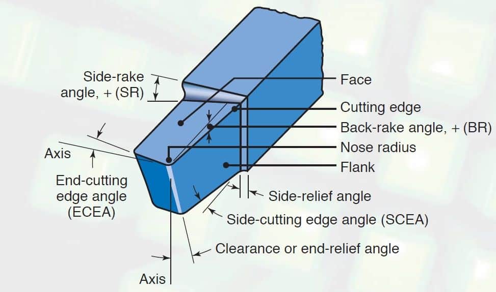
Diagram: Geometry of a Single Point Cutting Tool
2. Chip Formation in Metal Cutting
During machining, chips are formed as the cutting tool shears material away from the workpiece. The type of chip formed depends on the work material, cutting conditions, and tool geometry. The three primary types of chips are:
- Continuous Chips: Formed when the material flows smoothly without fracture. These are common when machining ductile materials.
- Discontinuous Chips: Produced when the material fractures ahead of the cutting tool. These occur in brittle materials or under poor cutting conditions.
- Built-Up Edge (BUE): A formation of material on the cutting tool edge due to excessive friction. BUE can negatively affect surface finish.
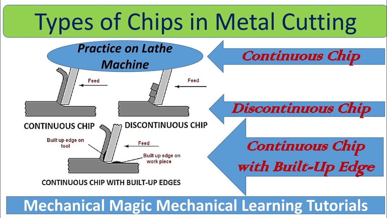
Diagram: Types of Chip Formation
3. Forces Acting on the Cutting Tool
During machining, the cutting tool experiences several forces. These forces affect tool wear, cutting efficiency, and the final surface finish. The primary forces acting on the tool are:
- Cutting Force (Fc): The force acting tangentially to the cutting surface. It is the largest force and is responsible for removing the material.
- Thrust Force (Ft): The force acting perpendicular to the cutting direction, pressing the tool into the workpiece.
- Radial Force (Fr): The force acting radially, pushing the tool away from the workpiece. It causes deflection and affects dimensional accuracy.
3.1 Measurement of Cutting Forces
Cutting forces can be measured using a dynamometer, which records the forces acting on the tool during machining. Understanding these forces is essential for optimizing cutting conditions, extending tool life, and improving productivity.
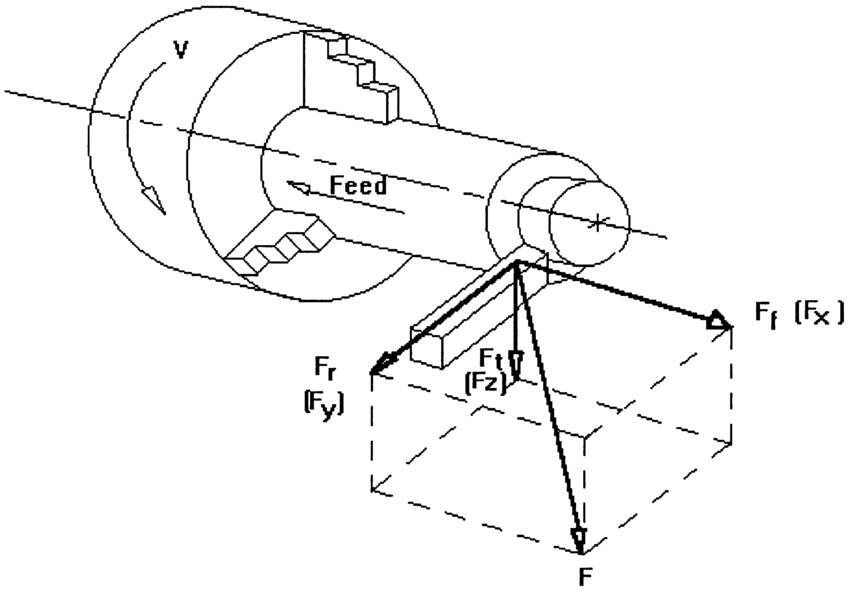
Diagram: Forces Acting on a Cutting Tool
4. Specific Cutting Energy
Specific cutting energy is the amount of energy required to remove a unit volume of material. It depends on factors like material properties, tool geometry, and cutting conditions. It is calculated as:
5. Plowing Force and the “Size Effect”
The plowing force occurs when the cutting edge of the tool does not penetrate the material fully and instead deforms the material surface. This causes an increase in cutting force without significant material removal. The “size effect” refers to the observation that the specific cutting energy increases as the uncut chip thickness decreases.
6. Mean Shear Strength of Work Material
The mean shear strength of the work material is the average shear stress required to shear the material during cutting. It can be estimated from the cutting forces and chip formation characteristics. It is given by:
Where:
- Φ = shear angle
- b = width of cut
- t = uncut chip thickness
7. Chip Thickness: Theory of Ernst and Merchant
The Ernst and Merchant theory explains chip formation in metal cutting by analyzing forces and energy in the cutting zone. According to this theory, the shear angle (Φ) is determined by the cutting conditions and tool geometry, and can be calculated using the formula:
Where:
- r = chip thickness ratio (tc/t)
- tc = chip thickness
- t = uncut chip thickness
- α = rake angle of the tool
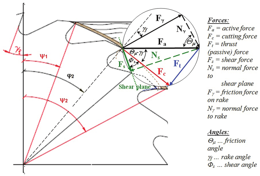
Diagram: Ernst and Merchant Chip Formation Model
8. Theory of Lee and Shaffer
The Lee and Shaffer theory builds upon the Ernst and Merchant theory by incorporating plastic deformation and work hardening of the material. It also considers the effect of cutting speed on shear strength and chip formation. This theory is particularly useful for predicting the behavior of difficult-to-machine materials.
Unit 3: Thermal Aspects, Tool Wear, and Machinability
Temperature in Metal Cutting
Metal cutting involves the interaction of the tool and the workpiece, which generates a significant amount of heat. This heat arises from three main sources:
- Plastic deformation of the material being cut in the shear zone.
- Friction between the chip and the tool face.
- Friction between the tool flank and the machined surface.
Heat Generation in Metal Cutting
The total heat generated during the cutting process can be expressed by the following formula:
Q = F_c \cdot v_c
Where:
- Q: Total heat generated (W)
- F_c: Cutting force (N)
- v_c: Cutting speed (m/s)
Most of this heat is concentrated in the chip, tool, and workpiece, causing a temperature rise.
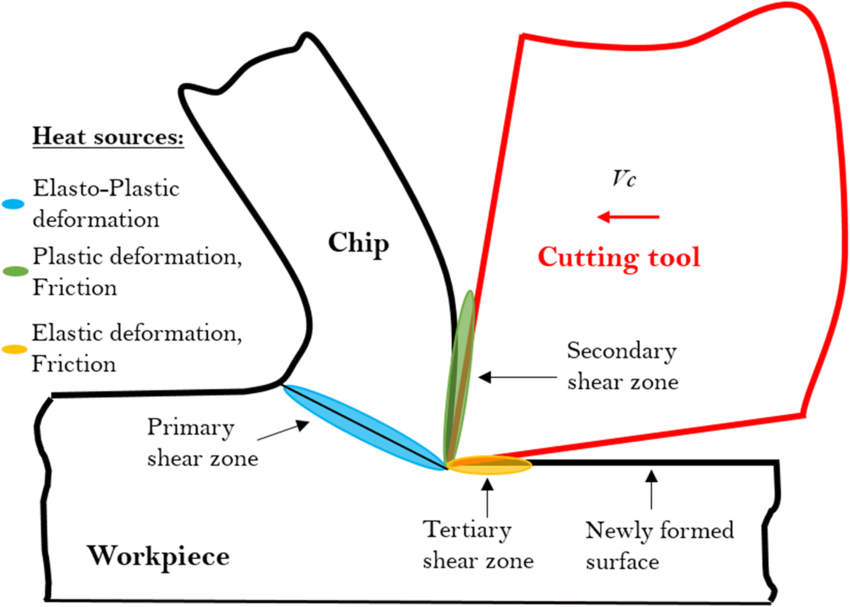
Figure 1: Heat Generation in the Metal Cutting Process
Temperature Distribution in Metal Cutting
The temperature distribution in metal cutting varies across the chip, tool, and workpiece. The highest temperature is found near the cutting edge of the tool, particularly on the tool rake face where the chip slides over the surface.
Effect of Cutting Speed on Temperatures
Cutting speed significantly affects the temperature during metal cutting. As the cutting speed increases, the temperature rises because the amount of heat generated increases with the higher rate of plastic deformation and friction.
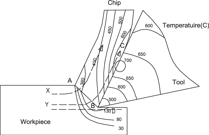
Figure 2: Effect of Cutting Speed on Temperature Distribution
Measurement of Cutting Temperatures
Several methods are used to measure cutting temperatures, including:
- Thermocouples: A junction of two different metals that produces a voltage proportional to the temperature difference.
- Infrared Thermography: A non-contact method that measures the infrared radiation emitted by the heated surface.
- Tool-Work Thermocouple Method: Measures the temperature at the tool-work interface using the junction between the tool and workpiece as a thermocouple.
Tool Life and Tool Wear
Tool life refers to the duration during which a cutting tool can be used before it must be replaced due to wear or failure. Progressive wear occurs gradually over time as the tool interacts with the workpiece material.
Forms of Wear in Metal Cutting
- Crater Wear: Occurs on the rake face of the tool due to the sliding action of the chip. It typically forms a depression or “crater.”
- Flank Wear: Occurs on the flank face of the tool due to friction between the tool and the machined surface. It leads to a gradual loss of material from the tool surface.
The rate of tool wear depends on several factors, including cutting speed, feed rate, tool material, and workpiece material.
Tool-Life Criteria
Tool life is often determined by a tool’s ability to maintain a sharp cutting edge. A commonly used criterion for tool life is the Taylor Tool Life Equation:
V_T^n = C
Where:
- V: Cutting speed (m/min)
- T: Tool life (minutes)
- n: Exponent (material-specific)
- C: Constant for a given tool-work material combination
Cutting Tool Materials
The material used to make cutting tools plays a crucial role in determining their performance. The basic requirements of cutting tool materials include:
- High hardness and wear resistance.
- Hot hardness (ability to retain hardness at high temperatures).
- Good toughness to withstand the forces during cutting.
- Chemical stability to avoid reactions with the workpiece material.
Major Classes of Tool Materials
The major classes of tool materials include:
- High-Speed Steel (HSS): Commonly used for drills, taps, and end mills. Offers good toughness and wear resistance but is limited in high-temperature applications.
- Cemented Carbide: Provides excellent hardness and wear resistance at high temperatures. It is commonly used in turning, milling, and drilling applications.
- Ceramics: Extremely hard and resistant to wear, making them suitable for high-speed cutting of hard materials.
- CBN (Cubic Boron Nitride): Second in hardness only to diamond. Used for machining hard materials like hardened steel and cast iron.
- Diamond: The hardest material known, used for machining non-ferrous metals, ceramics, and composites.
Tool Coatings
Tool coatings are applied to cutting tools to enhance their performance by reducing friction and wear. Common coatings include:
- TiN (Titanium Nitride): Increases wear resistance and reduces friction.
- TiC (Titanium Carbide): Offers higher hardness and wear resistance.
- Al2O3 (Aluminum Oxide): Improves hot hardness and chemical stability at high temperatures.
Use of Cutting Fluids
Cutting fluids are essential in metal cutting operations as they provide the following benefits:
- Cooling the cutting zone to reduce temperature and prevent tool wear.
- Lubricating to reduce friction between the tool and workpiece.
- Flushing away chips to prevent clogging and damage to the tool.
- Improving surface finish by reducing roughness caused by heat and friction.
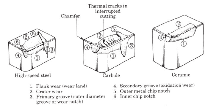
Figure 3: Cutting Tool Materials and Wear Mechanisms
Unit 4: Processing of Powder Metals
Introduction
Powder metallurgy is a manufacturing process that involves the production and shaping of metal powders to create parts and components. This method is particularly advantageous for producing complex shapes with high precision, minimizing material waste, and enabling the use of materials that are difficult to process through traditional methods.
Production of Metal Powders
The production of metal powders can be achieved through several methods, which can be categorized into two main groups: physical and chemical methods.
Methods of Powder Production
- Atomization: Liquid metal is sprayed into fine droplets that solidify to form powders. This method is widely used for metals like steel and aluminum.
- Mechanical Milling: Bulk metal is reduced to powder form using mechanical forces, such as ball milling.
- Chemical Reduction: Metal oxides are reduced to metal powders using reducing agents.
- Electrolysis: Metal ions are deposited onto a cathode from a solution, forming powders.
- Gas Phase Reduction: Metal vapors are reacted in a controlled environment to form powders.
Particle Size, Shape, and Distribution
The characteristics of metal powders, including particle size, shape, and distribution, significantly influence the final properties of the sintered parts. The size is typically measured in micrometers (µm) and can affect properties like flowability and packing density.
- Particle Size: Smaller particles generally lead to better sintering and density but may affect flowability.
- Particle Shape: Spherical particles are often preferred for their flow characteristics, while irregular shapes may enhance packing density.
- Particle Distribution: A mix of different sizes can improve packing efficiency, leading to better sintering outcomes.
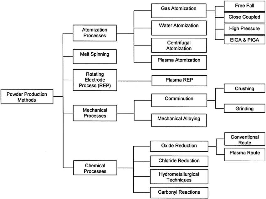
Figure 1: Methods of Powder Production
Blending Metal Powders
Blending involves mixing different metal powders to achieve desired compositions and properties. This step is crucial for producing alloys and ensuring uniformity in the powder mixture, which directly impacts the quality of the final product.
Compaction of Metal Powders
After blending, the metal powders must be compacted into a desired shape. Compaction can significantly affect the density and mechanical properties of the final product.
Equipment
Common equipment used for compaction includes:
- Hydraulic Presses: Use hydraulic pressure to compact the powder into molds.
- Mechanical Presses: Employ mechanical force for the compaction process.
- Isostatic Pressing Equipment: Applies uniform pressure from all directions, improving density and uniformity.
Isostatic Pressing
Isostatic pressing involves applying equal pressure in all directions to achieve uniform density. This method is particularly useful for complex shapes and ensures that the compacted powder maintains its integrity during the subsequent sintering process.
Sintering
Sintering is a crucial step that involves heating the compacted powders below their melting point to form a solid mass. During this process, particles bond together through diffusion, resulting in increased strength and density.
- Advantages of Sintering: Produces parts with minimal porosity, improved mechanical properties, and dimensional accuracy.
- Temperature Control: The sintering temperature and time must be carefully controlled to achieve the desired properties without compromising the part.
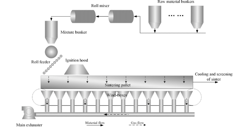
Figure 2: The Sintering Process in Powder Metallurgy
Secondary and Finishing Operations
After sintering, additional operations may be necessary to achieve the desired final properties and dimensions. These operations may include:
- Machining: To achieve tighter tolerances or improve surface finish.
- Heat Treatment: To enhance mechanical properties such as hardness and strength.
- Coating: To improve wear resistance or corrosion protection.
- Testing and Inspection: Ensuring that the final product meets specified requirements.
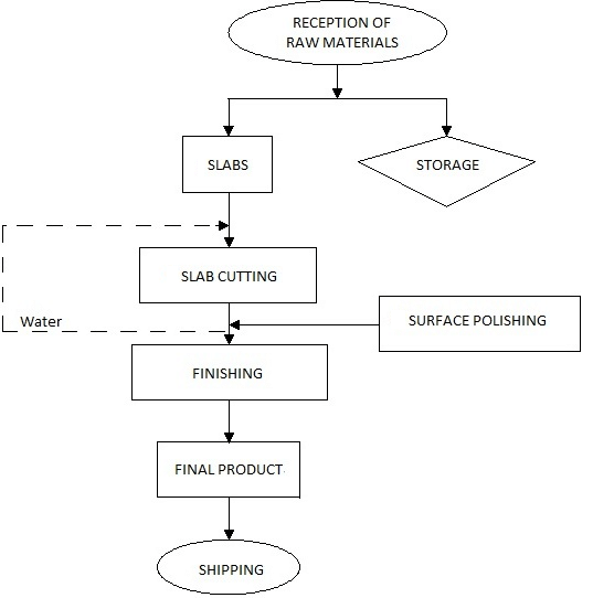
Figure 3: Secondary and Finishing Operations in Powder Metallurgy
Unit 5: Processing of Plastics, Ceramics, and Glasses
Plastics: Introduction
Plastics are synthetic materials made from polymers, which are long chains of molecules. They are versatile, lightweight, and can be molded into various shapes, making them suitable for numerous applications. The processing of plastics involves several techniques that allow for the shaping and finishing of plastic materials.
Extrusion
Extrusion is a continuous process where plastic is melted and forced through a die to produce a specific cross-sectional profile. This method is widely used for creating items like pipes, sheets, and films.
Miscellaneous Extrusion Processes
- Sheet Extrusion: Produces flat sheets of plastic, often used for packaging and signs.
- Pipe Extrusion: Used to create various types of pipes for plumbing and industrial applications.
- Blown Film Extrusion: Produces thin films for packaging by blowing air into the molten tube.
Production of Polymer Reinforcing Fibers
This process involves creating fibers from polymer materials to reinforce plastics, enhancing their mechanical properties. These fibers can be added to plastic matrices to improve strength, stiffness, and durability.
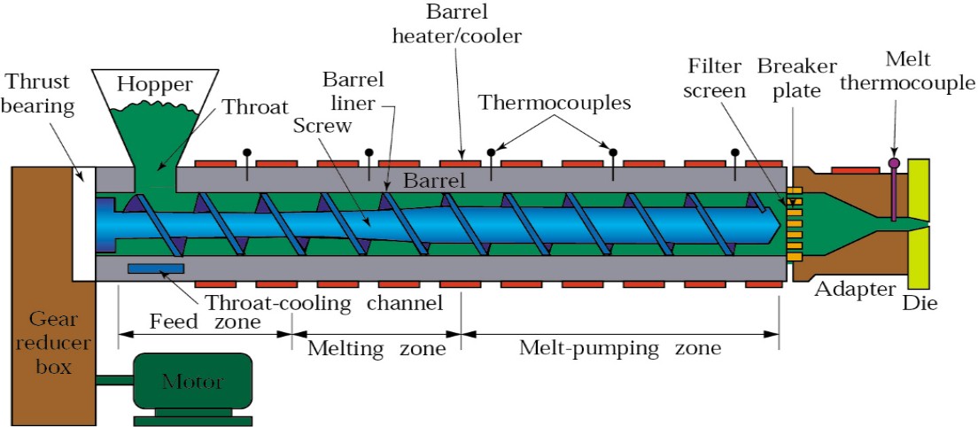 Figure 1: Extrusion Process for Plastics
Injection Molding
Injection molding is a widely used manufacturing process for producing parts by injecting molten plastic into a mold. It is ideal for producing complex shapes with high precision and repeatability.
Reaction-Injection Molding
This variation involves mixing two reactive components, which chemically react and solidify in the mold. It is often used for producing polyurethane parts, such as foam seating and insulation materials.
Blow Molding
Blow molding is used to create hollow plastic parts by inflating a heated plastic tube (parison) inside a mold. Common applications include bottles and containers.
Rotational Molding
In this process, powdered plastic is placed in a mold, which is heated and rotated to distribute the material evenly across the mold surfaces. This technique is suitable for large, hollow objects like storage tanks and playground equipment.
Thermoforming
Thermoforming involves heating a plastic sheet until pliable and then forming it over a mold. This method is often used for packaging and disposable products, such as trays and cups.
Compression Molding
Compression molding involves placing plastic material into an open mold, which is then closed and heated to allow the plastic to flow and take the shape of the mold. This method is commonly used for producing items like automotive parts and electrical housings.
Transfer Molding
Transfer molding is similar to compression molding but involves transferring heated plastic from a separate chamber into the mold. This method is suitable for creating complex shapes and is often used for thermosetting plastics.
Casting
Casting is a process where liquid plastic is poured into a mold and allowed to cure. This method is used for producing items like jewelry, custom parts, and decorative items.
Foam Molding
Foam molding involves creating lightweight plastic products filled with air or gas. This process is commonly used for packaging materials, insulation, and cushioning products.
Cold Forming and Solid-Phase Forming
These processes involve shaping plastics at room temperature without melting them. Cold forming is often used for creating thin sheets, while solid-phase forming is used for thicker sections requiring minimal distortion.
Processing Elastomers
Elastomers, or rubber-like materials, are processed using techniques like injection molding and extrusion. These materials exhibit high elasticity and are used in products like seals, gaskets, and tires.
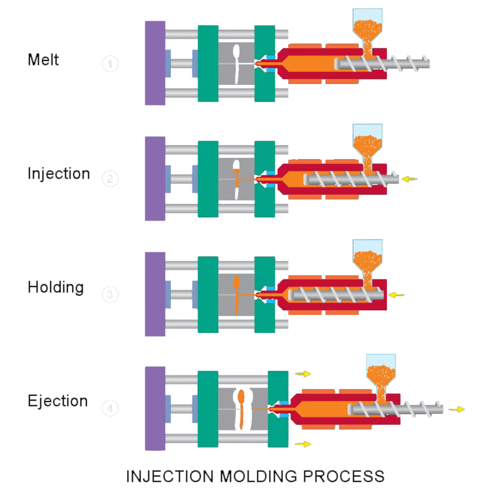 Figure 2: Injection Molding Process
Ceramics and Glasses
Ceramics are inorganic, non-metallic materials that are typically made by shaping and then firing a non-metallic mineral, such as clay, at high temperatures. They are known for their hardness, high melting points, and resistance to chemical attack.
Processing of Ceramics
The processing of ceramics generally includes the following steps:
- Powder Preparation: Selecting and processing raw materials into fine powders.
- Shaping: Using methods such as pressing, extrusion, or casting to shape the ceramic material.
- Sintering: Heating the shaped material to form a dense, solid structure.
Processing of Glasses
Glass is typically processed through melting silica sand and other additives at high temperatures. Once melted, it can be shaped through blowing, pressing, or molding.
- Annealing: Gradually cooling the glass to relieve internal stresses.
- Finishing: Cutting, polishing, or coating the glass to achieve desired properties.
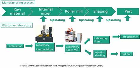 Figure 3: Processing of Ceramics and Glasses
Texts:
- Serope Kalpakjian and Steven R. Schmid, “Manufacturing Engineering and Technology”, Addison Wesley Longman (Singapore) Pte. India Ltd., 6th edition, 2009.
- Geoffrey Boothroyd, Winston Knight, “Fundamentals of Machining and Machine Tools”, Taylor and Francis, 3rd edition, 2006.
References:
- Milkell P. Groover, “Fundamentals of Modern Manufacturing: Materials, Processes, and Systems”, John Wiley and Sons, New Jersey, 4th edition, 2010.
- Paul De Garmo, J. T. Black, Ronald A. Kohser, “Materials and Processes in Manufacturing”, Wiley, 10th edition, 2007.
- M. C. Shaw, “Theory of Metal Cutting”, Oxford and I.B.H. Publishing, 1st edition, 1994.