Manufacturing Processes-I
Unit 1: Introduction and Casting Processes
1. What is Manufacturing?
Manufacturing is the process of converting raw materials into finished products using various techniques. It involves various stages, from material selection to production, with the aim of producing goods efficiently and effectively.
2. Selection of Manufacturing Processes
The selection of appropriate manufacturing processes is crucial for producing components with the required specifications, cost-effectiveness, and quality. Factors considered in selection include:
- Material properties
- Design complexity
- Production volume
- Cost constraints
- Lead time requirements
3. Introduction to Casting
Casting is one of the oldest manufacturing processes where molten metal is poured into a mold, allowed to solidify, and then removed from the mold to form a part. It is widely used to create components with complex geometries.
4. Solidification of Metals
4.1 Solidification of Pure Metals
When a pure metal solidifies, the process begins with nucleation, followed by grain growth. The metal solidifies at a constant temperature, and the final structure is made of equiaxed grains.
4.2 Solidification of Alloys
Alloys, unlike pure metals, solidify over a range of temperatures. The solidification process involves the formation of dendrites, which create a microstructure of varying compositions.
5. Fluid Flow and Fluidity of Molten Metal
Fluidity refers to the ability of molten metal to fill a mold. Factors influencing fluidity include:
- Metal composition
- Pouring temperature
- Mold material and design
- Rate of solidification
6. Heat Transfer
6.1 Solidification Time
Solidification time, according to Chvorinov’s rule, is given by the formula:
- t_s: Solidification time
- C: Mold constant
- V: Volume of the casting
- A: Surface area of the casting
6.2 Shrinkage
During solidification, metals experience shrinkage, which can lead to defects like voids or cracks. Proper gating and riser design help compensate for shrinkage.
7. Casting Defects: Porosity
Porosity is a common defect in castings caused by trapped gas or shrinkage. It results in small voids or holes in the final product, reducing its strength and durability. Proper control of melting, pouring, and mold design helps minimize porosity.
8. Metal Casting Processes
8.1 Sand Casting
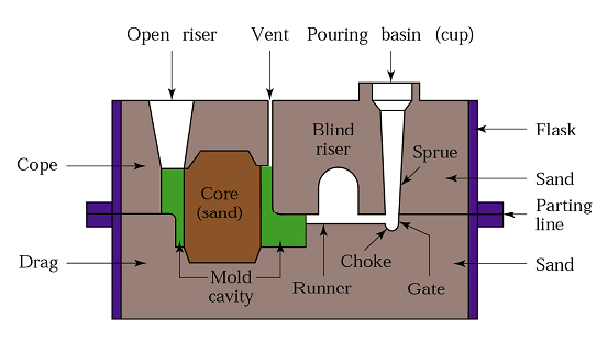
Sand casting is a versatile process where a mold made of sand is used. The molten metal is poured into the sand mold, allowed to solidify, and then the casting is removed. It is suitable for large and complex parts.
8.2 Shell Molding
Shell molding involves creating a mold by covering a heated metal pattern with sand and resin. This method provides better accuracy and surface finish compared to sand casting.
8.3 Investment Casting
Investment casting, also known as lost-wax casting, involves creating a wax pattern which is coated with refractory material. The wax is melted away, and molten metal is poured into the resulting cavity. This process is ideal for intricate and precise components.
8.4 Permanent-Mold Casting
In permanent-mold casting, the mold is made of metal and can be reused multiple times. This process is faster and provides better dimensional accuracy than sand casting but is limited to simpler shapes.
8.5 Vacuum Casting
Vacuum casting involves pouring molten metal into a mold inside a vacuum chamber. This process reduces the risk of gas entrapment and results in high-quality castings.
8.6 Die Casting
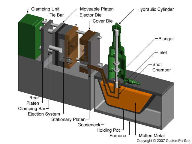
Die casting is a high-pressure casting process where molten metal is forced into a mold cavity under high pressure. It is commonly used for producing large quantities of small to medium-sized parts with excellent surface finish.
8.7 Centrifugal Casting
Centrifugal casting involves rotating the mold during the pouring process, which forces the molten metal to the outer walls of the mold. This method is ideal for creating cylindrical components like pipes and bearings.
Understanding the various casting processes and their intricacies is essential for selecting the right process based on the design, material, and cost requirements. Each process has its advantages and limitations, and proper control over fluid flow, heat transfer, and shrinkage is critical for producing high-quality castings.
Unit 2: Metal Forming
a) Rolling and Forging Processes
1. Introduction to Rolling
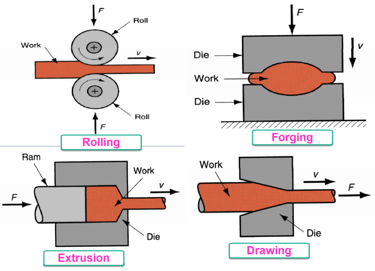
Rolling is a metal forming process where metal is passed through a pair of rolls to reduce its thickness and shape it into a desired profile. It is commonly used for producing sheets, plates, and structural shapes.
2. Flat-Rolling Process
In the flat-rolling process, metal is passed between two parallel rolls. The key aspects to consider are:
- Roll Force: The force required to deform the metal and overcome friction.
- Torque: The twisting force needed to rotate the rolls.
- Power Requirements: The total power required to perform the rolling operation.
- Geometric Considerations: The roll gap, entry and exit angles, and the shape of the rolls.
3. Flat-Rolling Practice
Defects in rolled plates and sheets can include:
- Surface Defects: Such as scratches, pits, and cracks.
- Dimensional Defects: Such as out-of-tolerance thickness and width.

4. Rolling Mills
Various types of rolling mills are used depending on the material and desired product, including:
- Two-high Mills: The simplest type, used for general rolling.
- Four-high Mills: Includes two small rolls and two large rolls to reduce rolling force.
- Sendzimir Mills: Features a cluster of rolls to achieve very thin sheets.
5. Introduction to Forging
Forging is a process where metal is shaped by applying compressive forces. It improves mechanical properties and is used for producing strong and durable components.
6. Forging Types
- Open-Die Forging: Metal is deformed between two flat dies. It is suitable for large components.
- Impression-Die Forging: Metal is placed in a die with an impression, resulting in more complex shapes.
- Closed-Die Forging: Metal is completely enclosed in a die, allowing for precise control over shape and size.
7. Forging Operations
Common forging operations include:
- Upsetting: Increasing the diameter of a metal piece.
- Drawing Out: Elongating a metal piece.
- Extrusion: Pushing metal through a die to form long shapes.
8. Forging Defects
Defects in forging can include:
- Surface Cracks: Resulting from excessive deformation or improper cooling.
- Internal Voids: Due to trapped gases or incomplete filling of the die.
9. Forging Machines
Forging machines include:
- Hammer Forging Machines: Use a hammer to apply force.
- Press Forging Machines: Apply force gradually through a press.
b) Extrusion and Drawing
1. Introduction to Extrusion
Extrusion involves forcing metal through a die to create long shapes with a consistent cross-section. It is used for making components like pipes, rods, and profiles.
2. Extrusion Process
In extrusion, the metal is heated and pushed through a die. The key types include:
- Hot Extrusion: Performed at high temperatures, which allows for easier deformation and better material flow.
- Cold Extrusion: Performed at room temperature, which improves surface finish and dimensional accuracy.
3. Extrusion Methods
- Impact Extrusion: Uses a high-speed punch to force the metal through the die.
- Hydrostatic Extrusion: Uses hydraulic pressure to push the metal through the die, reducing friction and improving surface quality.
4. Extrusion Defects
Common defects include:
- Surface Cracks: Resulting from excessive temperature or improper die design.
- Dimensional Variations: Due to inconsistencies in the extrusion process.
5. Extrusion Equipment
Extrusion equipment includes:
- Extrusion Presses: Machines that push the metal through the die.
- Dies: Tools used to shape the extruded metal.
6. Introduction to Drawing
Drawing is a process where metal is pulled through a die to reduce its diameter and increase its length. It is commonly used for producing wire and tube products.
7. Drawing Process
The drawing process involves:
- Wire Drawing: Reduces the diameter of wire.
- Tube Drawing: Reduces the diameter of tubes.
8. Drawing Practice
Key considerations in drawing include:
- Lubrication: Reduces friction and wear during the drawing process.
- Die Design: Ensures proper shaping and dimensional accuracy.
9. Drawing Defects
Common defects include:
- Surface Defects: Such as scratches and deformation.
- Residual Stresses: Resulting from uneven cooling or improper processing.
10. Drawing Equipment
Drawing equipment includes:
- Drawing Machines: Used to pull the metal through the die.
- Dies: Tools that shape the drawn metal.
Unit 3: Joining Processes
1. Oxy-Fuel-Gas Welding
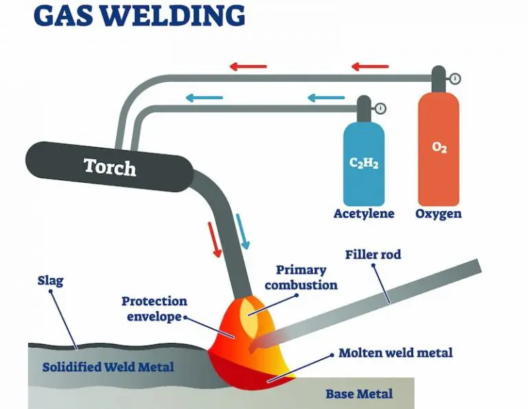
Oxy-fuel-gas welding, also known as oxy-acetylene welding, uses a mixture of oxygen and fuel gas to produce a flame that melts the metal for joining. It is commonly used for welding and cutting metals.
2. Arc-Welding Processes
2.1 Non-Consumable Electrode Welding
In non-consumable electrode welding, the electrode does not melt and become part of the weld. Examples include:
- Tungsten Inert Gas (TIG) Welding: Uses a tungsten electrode to produce the weld.

2.2 Consumable Electrode Welding
In consumable electrode welding, the electrode melts and becomes part of the weld. Examples include:
2.2.1 Shielded Metal-Arc Welding (SMAW)
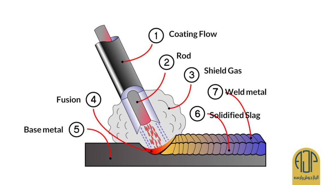
Also known as stick welding, SMAW uses a consumable electrode covered with a flux to shield the weld from contaminants.
2.2.2 Submerged-Arc Welding (SAW)
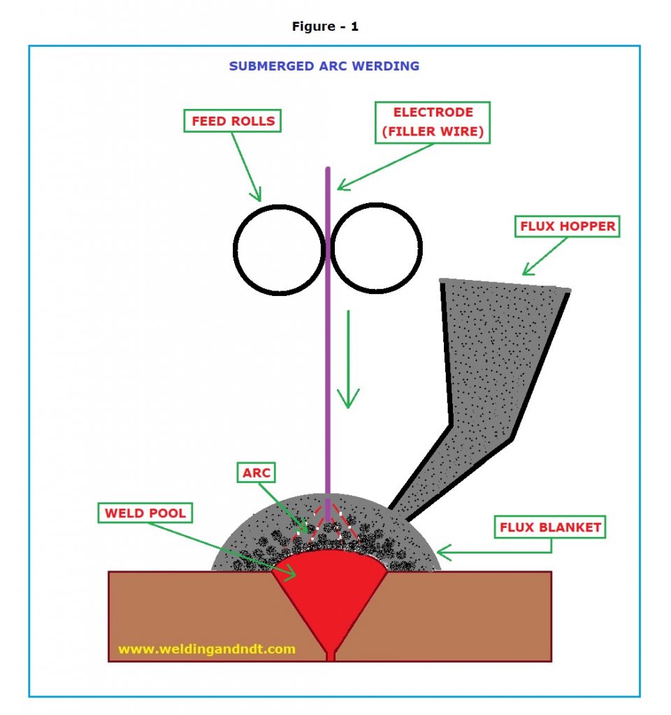
SAW involves a continuously fed consumable electrode and a blanket of flux that submerges the arc, protecting it from contaminants.
2.2.3 Gas Metal-Arc Welding (GMAW)
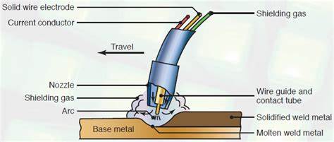
Also known as MIG welding, GMAW uses a continuously fed consumable wire electrode and an inert gas to protect the weld pool.
2.3 Electrodes for Arc Welding
Electrodes for arc welding are classified into:
- Consumable Electrodes: Melt and become part of the weld.
- Non-Consumable Electrodes: Do not melt and remain intact during welding.
3. The Weld Joint
A weld joint is the location where two or more pieces of metal are joined by welding. Key aspects include:
- Weld Quality: Refers to the integrity and strength of the weld.
- Weldability: The ease with which a material can be welded.
3.1 Quality and Testing
Weld quality is assessed through various testing methods including:
- Visual Inspection: Checking for visible defects.
- Non-Destructive Testing (NDT): Methods like ultrasonic and radiographic testing to detect internal flaws.
4. Introduction to Solid State Welding
Solid-state welding processes join materials without melting them, relying on pressure and/or temperature. Key processes include:
4.1 Friction Welding
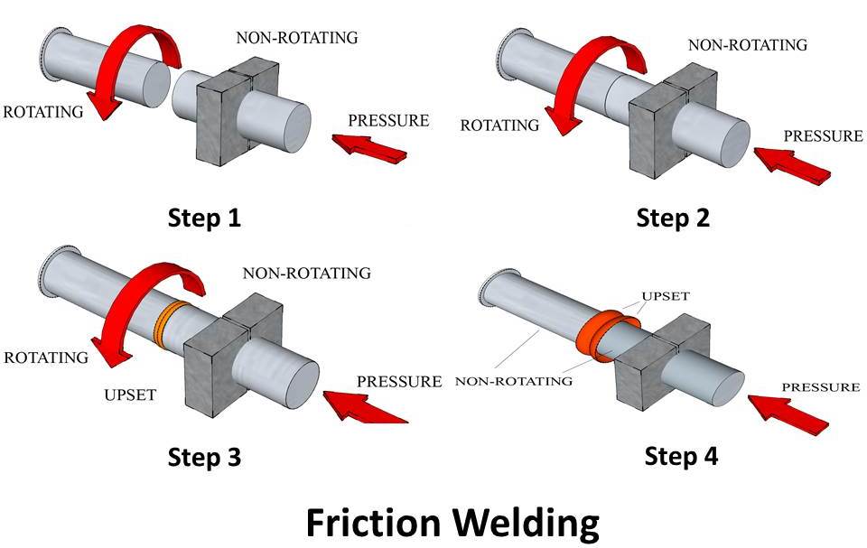
Friction welding uses the heat generated by friction to join materials. One part rotates while the other remains stationary.
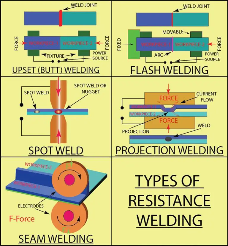
4.2 Resistance Welding
- Spot Welding: Joins metal pieces at localized spots using heat and pressure.
- Seam Welding: Creates a continuous weld along a seam.
- Projection Welding: Uses projections on one workpiece to localize the weld.
5. Introduction to Brazing and Soldering
Brazing and soldering are joining processes that use filler metals with lower melting points than welding.
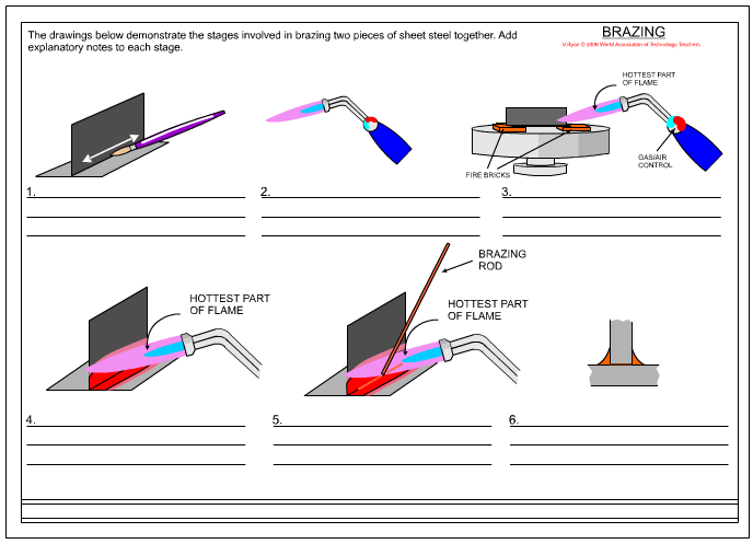
5.1 Brazing
Brazing involves joining metals using a filler metal with a melting point above 450°C (842°F) but below the melting point of the base metals.
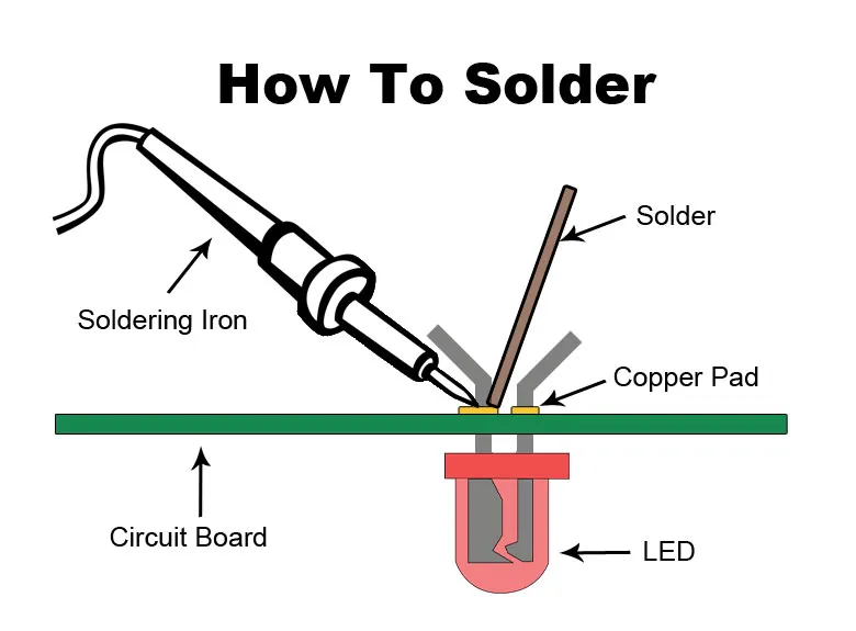
5.2 Soldering
Soldering uses a filler metal with a melting point below 450°C (842°F) to join metals. It is commonly used for electrical connections and small components.
Unit 4: Machining Processes: Turning and Hole Making
1. Introduction
Machining processes are essential for creating precise and accurate parts in manufacturing. This unit focuses on turning and hole-making processes, which are crucial for shaping and drilling operations.
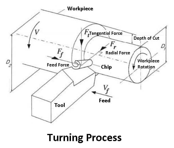
2. The Turning Process
Turning is a machining process used to produce cylindrical parts by cutting away material from a rotating workpiece. It involves various lathe operations and accessories.
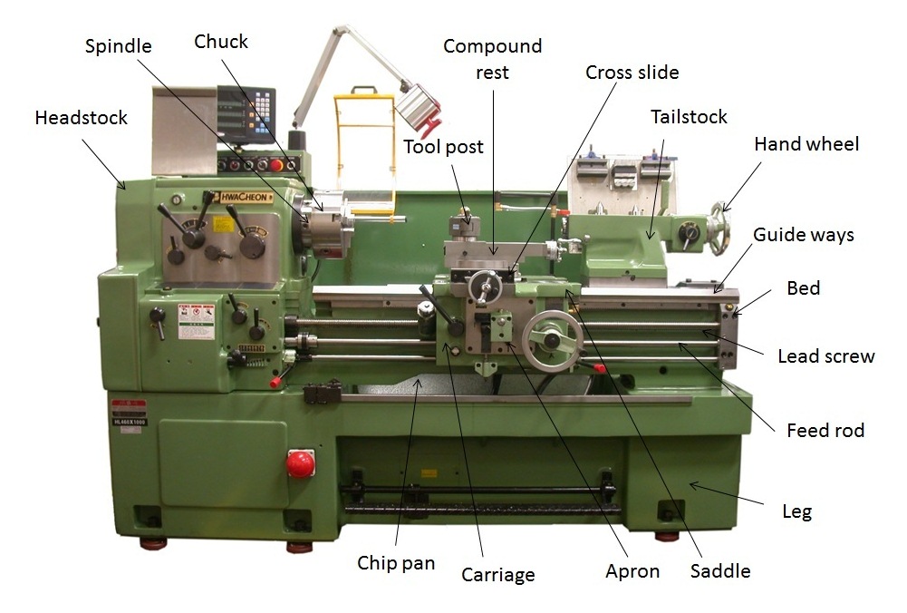
2.1 Lathe Components
A lathe machine consists of several key components:
- Bed: The base of the lathe that supports all other components.
- Headstock: Contains the spindle and gear mechanisms.
- Tailstock: Provides support for the other end of the workpiece.
- Carriage: Moves along the bed to hold and control the cutting tool.
- Cross Slide: Allows the cutting tool to move perpendicular to the axis of rotation.
2.2 Work Holding Devices and Accessories
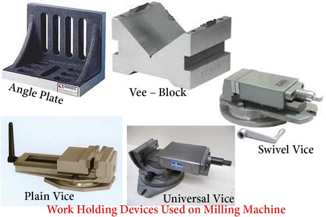
Work holding devices and accessories are used to secure and position the workpiece for machining:
- Chuck: Holds the workpiece in place.
- Tailstock: Supports the workpiece and can hold tools or centers.
- Tool Post: Holds the cutting tool in position.
2.3 Lathe Operations
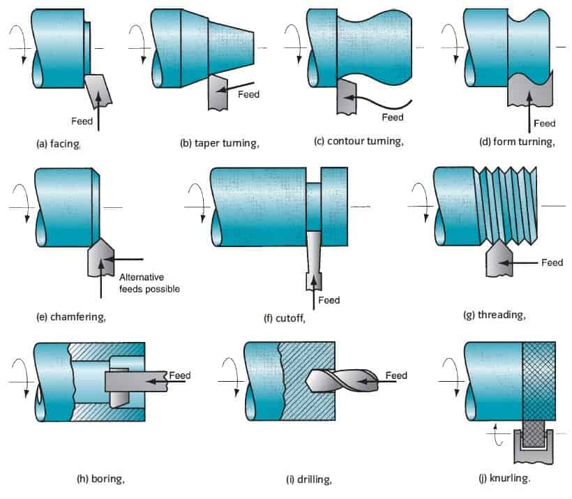
Lathe operations include various techniques used to shape the workpiece:
- Turning: Reduces the diameter of the workpiece.
- Facing: Creates a flat surface on the end of the workpiece.
- Drilling: Creates holes in the workpiece.
- Threading: Cuts threads into the workpiece.
2.4 Types of Lathes
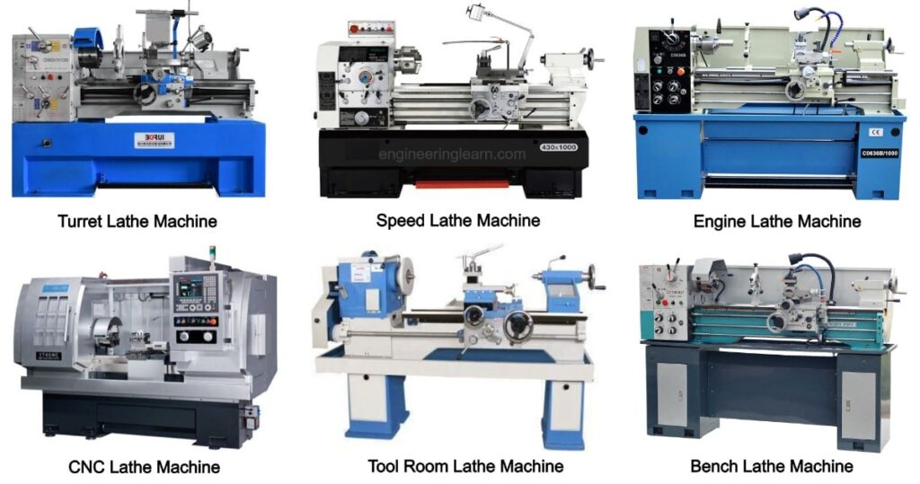
Different types of lathes are used for various applications:
- Engine Lathe: A versatile lathe used for a wide range of operations.
- CNC Lathe: A computer-controlled lathe for high precision and automation.
- Turret Lathe: Equipped with a turret for multiple tools and operations.
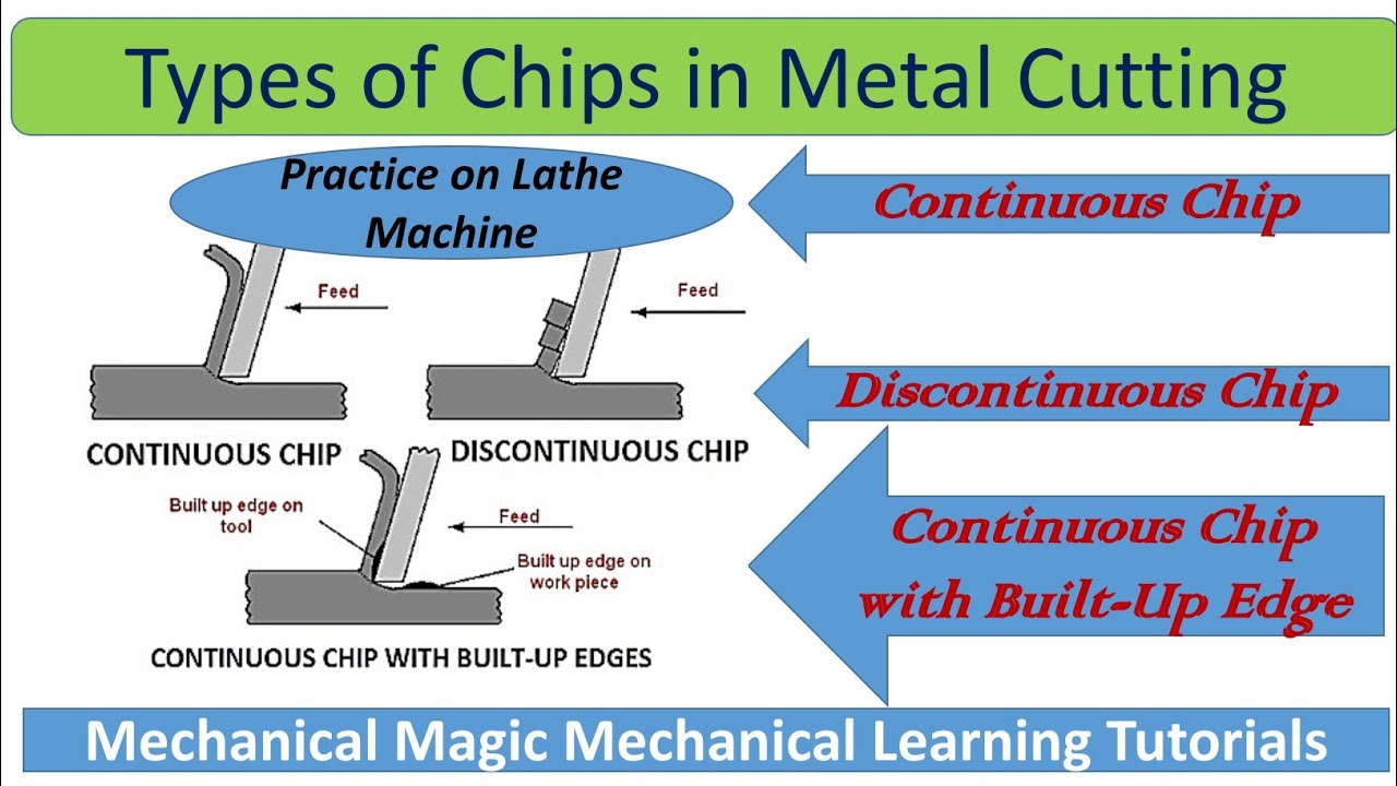
3. Types of Chips
Chips are the byproducts of the cutting process, and their types include:
- Continuous Chips: Formed when cutting with a sharp tool and high cutting speed.
- Discontinuous Chips: Formed with low cutting speeds and brittle materials.
- Segmented Chips: Formed when cutting with a dull tool or at a high speed.
4. Boring and Boring Machines
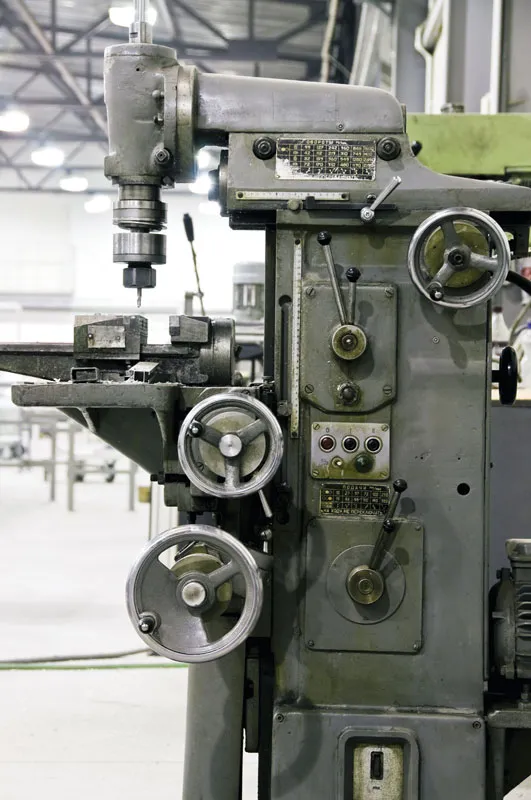
Boring is used to enlarge existing holes with high accuracy. Boring machines are designed for this purpose.
5. Drilling Machines
5.1 Drills
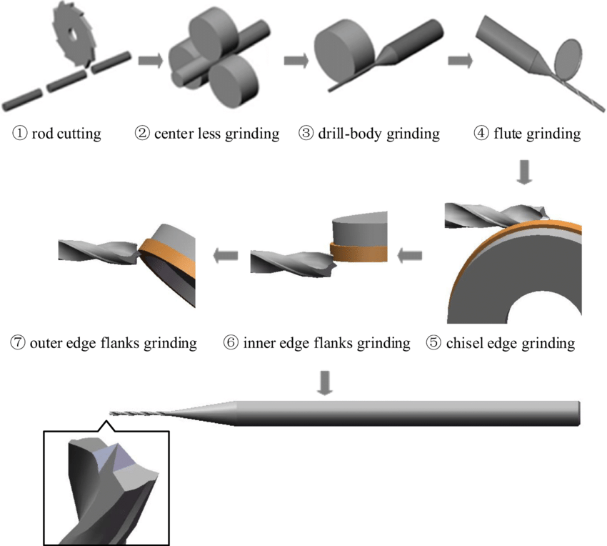
Drills are tools used to create holes in materials. They come in various types and sizes:
- Twist Drill: Commonly used for drilling metal and wood.
- Spade Drill: Used for large holes in wood.
- Center Drill: Used for creating a starting point for other drills.
5.2 Drill Materials and Sizes
Drills are made from various materials including high-speed steel (HSS) and carbide. Sizes vary based on the application.
5.3 Drilling Practice
Drilling practice involves proper techniques to achieve accurate holes:
- Speed: Adjust the drill speed based on material and drill size.
- Feed Rate: Control the rate at which the drill advances into the material.
- Coolant: Use coolant to reduce heat and improve drill life.
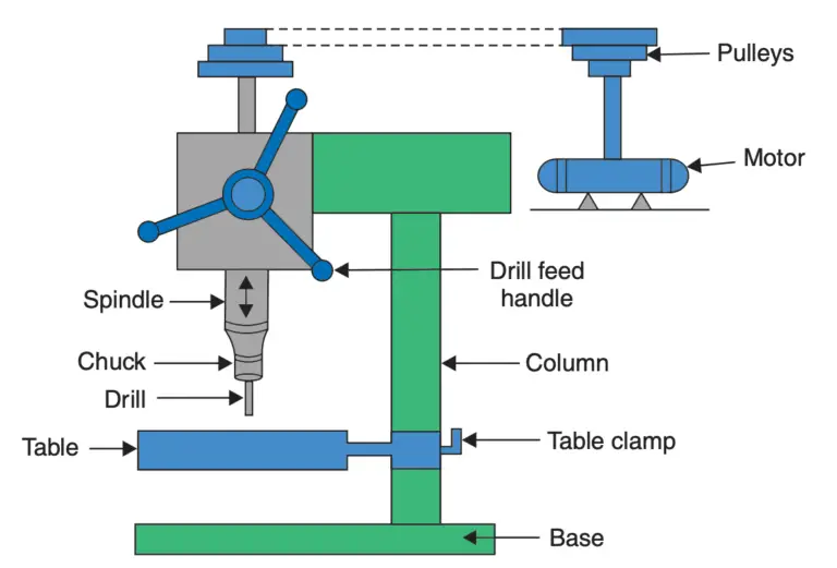
5.4 Drilling Machines
Drilling machines include:
- Bench Drill: A small drill press for light drilling tasks.
- Pillar Drill: A larger drill press for more robust drilling operations.
- CNC Drilling Machine: Computer-controlled for high precision drilling.
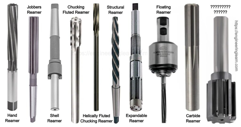
6. Reaming Operation and Reamers
Reaming is used to achieve a precise diameter and smooth surface finish in drilled holes. Reamers are tools used for this process.
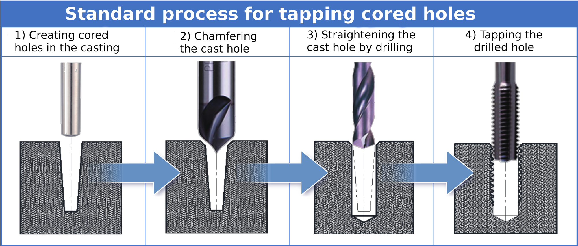
7. Tapping and Taps
Tapping is used to create internal threads in holes. Taps are tools used for this purpose and come in different types and sizes:
- Hand Taps: Used for manual threading.
- Machine Taps: Used in automated processes.
- Pipe Taps: Used for creating threads in pipes.
Unit 5: Machining Processes: Milling, Broaching, and Gear Manufacturing
1. Introduction
This unit covers various machining processes including milling, broaching, and gear manufacturing. These processes are essential for creating complex and precise parts in manufacturing.
2. Milling and Milling Machines
Milling is a machining process that uses rotating cutting tools to remove material from a workpiece. It includes various operations and types of milling machines.
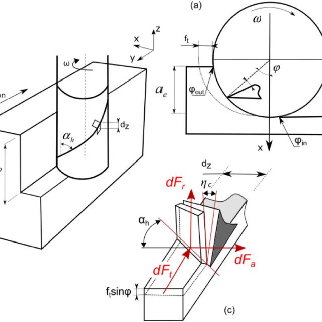
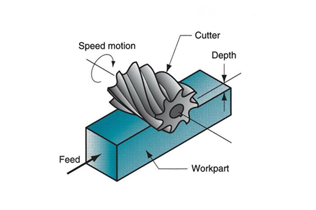
2.1 Peripheral Milling
Peripheral milling involves cutting with the peripheral edges of the cutter. It is used for producing slots, grooves, and shoulders in the workpiece.
 2.2 Face Milling
Face milling uses the flat face of the cutter to produce a flat surface on the workpiece. It is suitable for machining large, flat areas.
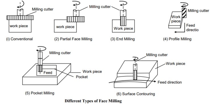
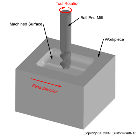
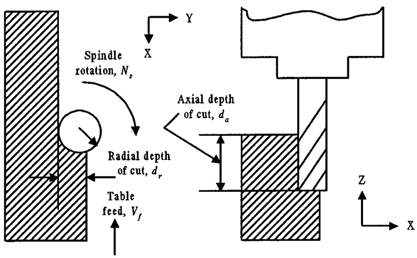
2.3 End Milling
End milling involves cutting with the end of the cutter and is used for creating pockets, contours, and complex shapes.
2.4 Other Milling Operations and Milling Cutters
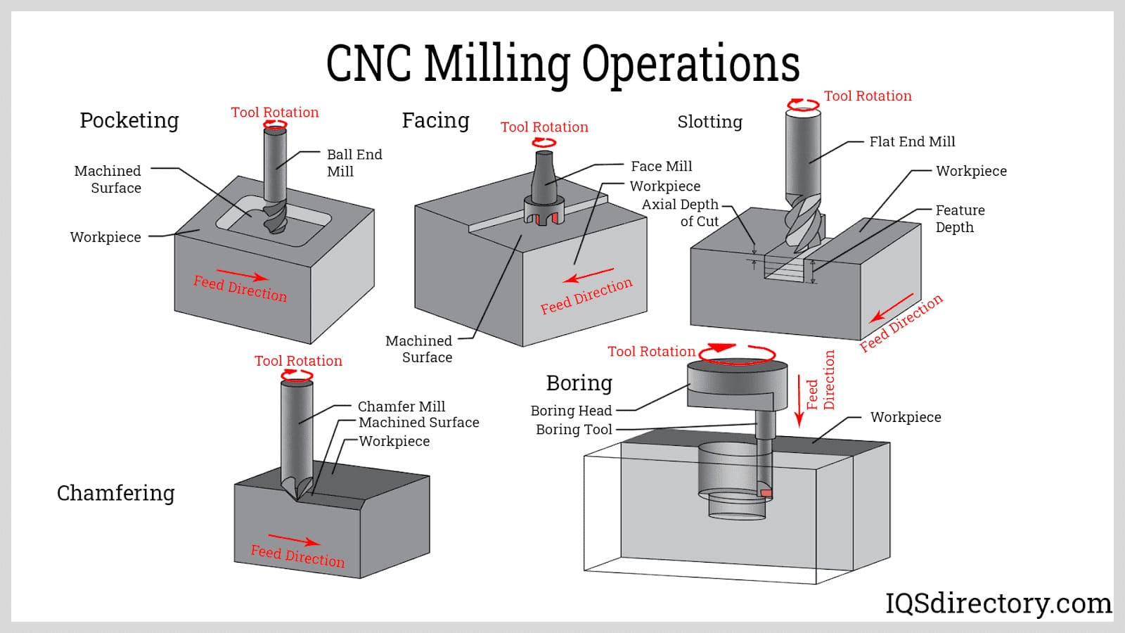
Various milling operations include slot milling, side milling, and straddle milling. Milling cutters come in different shapes and sizes for specific applications.
- Slot Milling: Produces slots in the workpiece.
- Side Milling: Used for cutting vertical surfaces.
- Straddle Milling: Cuts two parallel surfaces simultaneously.
2.5 Tool Holders
Tool holders are used to secure cutting tools in the milling machine. They come in various types including collet chucks and end mill holders.
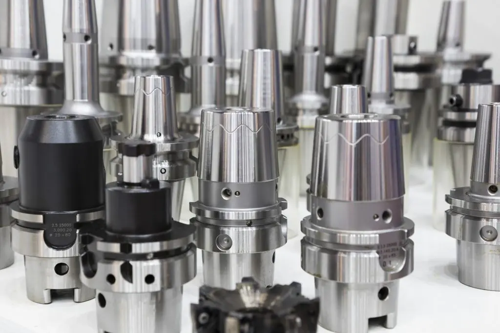
2.6 Milling Process Capabilities
The milling process can produce a wide range of features including slots, holes, and complex contours. Milling machines vary in size and capabilities to suit different manufacturing needs.
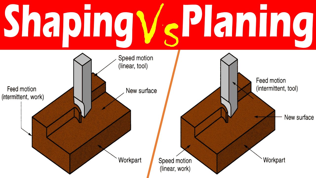
3. Planning and Shaping
Planning and shaping are processes used to cut flat surfaces and contours into the workpiece. They are typically used for less complex parts compared to milling.
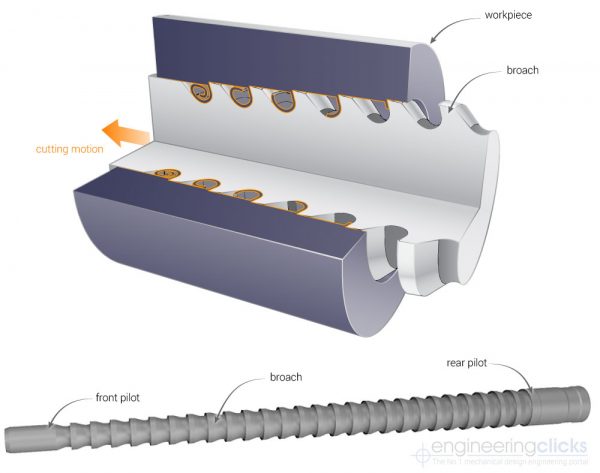
4. Broaching and Broaching Machines
Broaching is a machining process that uses a broach to remove material. It is used for creating precise and complex shapes in a single pass.
4.1 Types of Broaching Machines
- Vertical Broaching Machine: The broach moves vertically during the operation.
- Horizontal Broaching Machine: The broach moves horizontally.
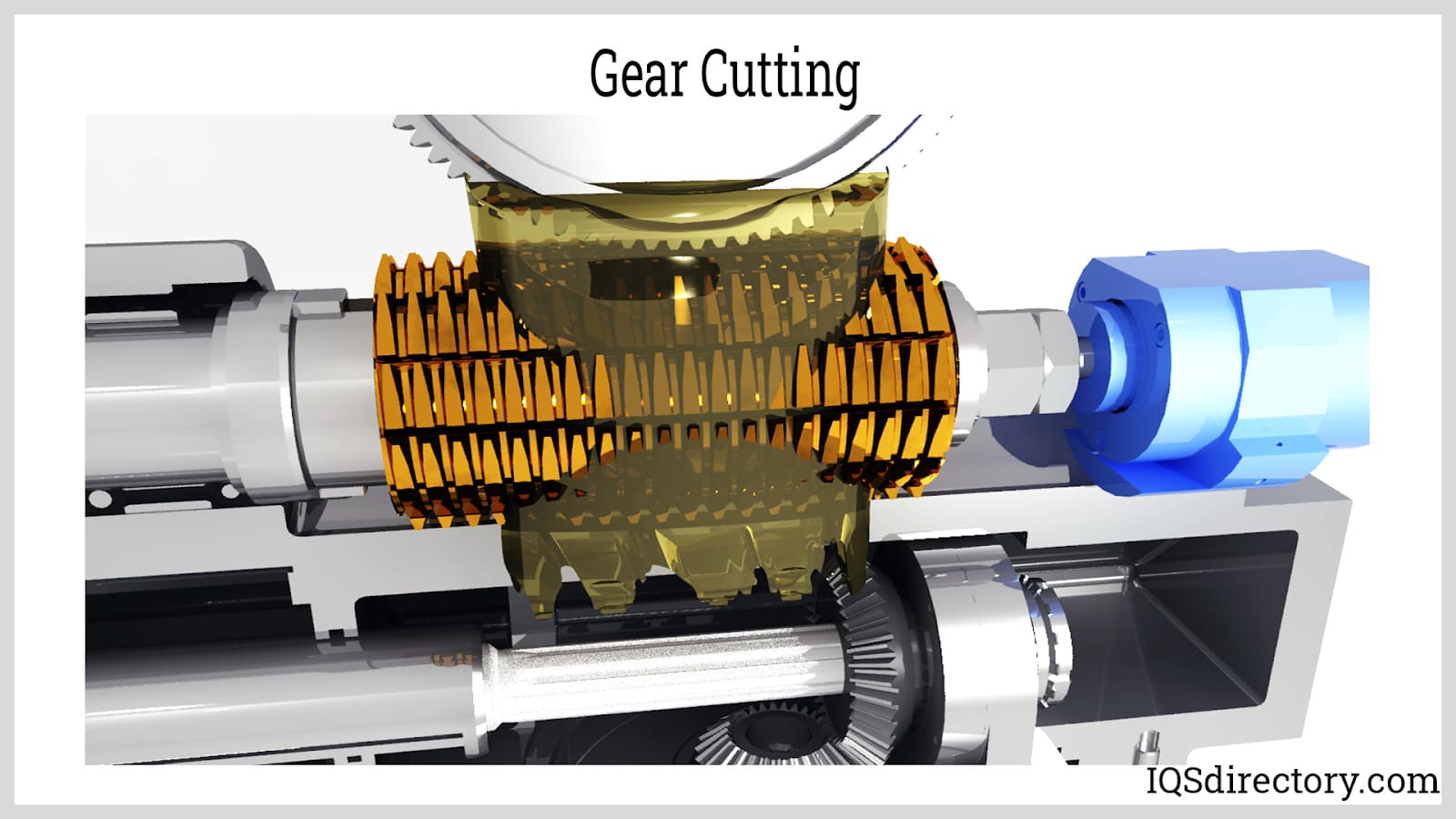
5. Gear Manufacturing by Machining
Gear manufacturing involves various processes to create gears with accurate tooth profiles and dimensions.
5.1 Form Cutting
Form cutting involves cutting gear teeth using a form cutter that matches the tooth profile.

5.2 Gear Generating
Gear generating uses a gear cutter to create gear teeth through a generating process that matches the gear’s tooth profile.
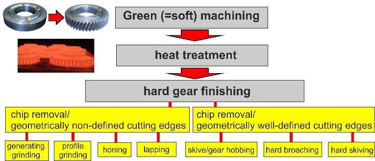
5.3 Cutting Bevel Gears
Bevel gears are cut using specialized bevel gear cutters or machines to create the angled teeth needed for bevel gear applications.
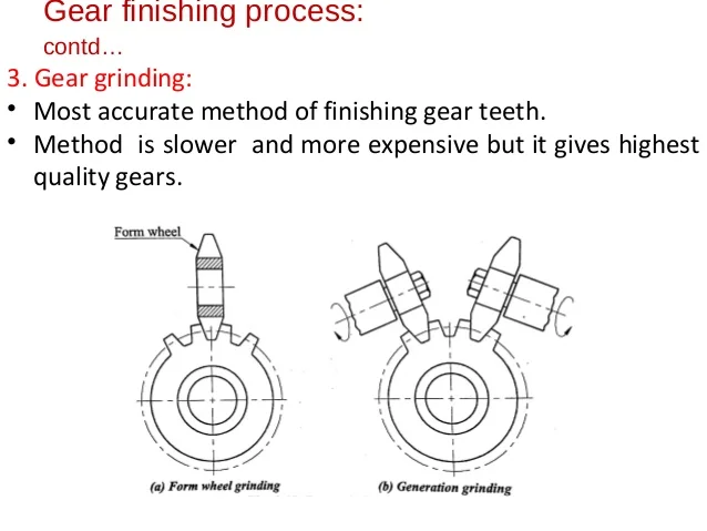
5.4 Gear-Finishing Processes
Gear-finishing processes include grinding and honing to achieve the final dimensions and surface finish of gears.
Text Books:
- Serope Kalpak Jain and Steven R. Schmid, “Manufacturing Engineering and Technology”, Addison Wesley Longman (Singapore) Pte. India Ltd., 6th edition, 2009.
References:
- Mikell P. Groover, “Fundamentals of Modern Manufacturing: Materials, Processes, and Systems”, John Wiley and Sons, New Jersey, 4th edition, 2010.
- Paul DeGarmo, J.T. Black, Ronald A. Kohser, “Materials and Processes in Manufacturing”, Wiley, 10th edition, 2007.
