Machine Design: 02
Unit 1: Rolling Contact Bearings
Introduction to Rolling Contact Bearings
Rolling contact bearings, commonly referred to as anti-friction bearings, are critical components in mechanical systems. They are designed to support and guide rotating shafts while significantly reducing friction between moving parts. This reduction in friction leads to increased efficiency, lower energy consumption, and extended service life of both the bearings and the machinery in which they are installed.
The operation of rolling contact bearings is based on the principle of rolling motion. By using rolling elements (such as balls or rollers), these bearings minimize the area of contact, which results in reduced friction compared to sliding contact bearings. This characteristic makes them suitable for a wide range of applications, from household appliances to heavy industrial machinery.
Types of Rolling Contact Bearings
Rolling contact bearings are classified into several types based on their design and functionality:
- Ball Bearings: These bearings use spherical balls as the rolling elements. They are versatile and can handle both radial and axial loads, making them suitable for high-speed applications.
- Roller Bearings: These bearings use cylindrical rollers. They are better suited for heavy radial loads and provide a larger contact area than ball bearings, which improves load distribution.
- Tapered Roller Bearings: Tapered roller bearings can accommodate both radial and axial loads due to their conical shape. They are ideal for applications where axial loads are present, such as automotive wheel hubs.
- Needle Bearings: These have long, thin rollers and are designed for applications where space is limited. They are particularly effective at handling radial loads.
- Self-aligning Ball Bearings: These bearings can accommodate misalignment between the shaft and housing, which is beneficial in applications where shaft deflection may occur.
Static and Dynamic Load Carrying Capacities
Understanding load capacities is essential for selecting the appropriate bearing for a given application. Load capacity can be classified into two main categories:
- Static Load Capacity (C0): This is the maximum load that a bearing can support without experiencing permanent deformation of its rolling elements or raceways. It is critical to consider the static load capacity when designing applications that may experience shock loads or sudden increases in load.
- Dynamic Load Capacity (C): This is the maximum load that a bearing can support while in motion. It directly influences the bearing’s life and performance under operating conditions. The dynamic load capacity is typically determined through testing and is expressed in units of force, such as newtons (N) or pounds (lb).
Stribeck’s Equation
Stribeck’s Equation describes the relationship between the friction coefficient of bearings and several variables, including load, speed, and lubrication conditions. It helps in understanding how friction varies in different operating environments:
μ = f(L, v, η)
Where:
- μ = Friction coefficient
- L = Load applied to the bearing
- v = Velocity of the bearing surfaces
- η = Viscosity of the lubricant used
Stribeck’s equation is particularly useful in analyzing the performance of bearings in varying operational conditions, allowing engineers to optimize bearing selection and lubrication strategies for different applications.
Equivalent Load
The equivalent load Peq is a calculated load that combines radial and axial loads acting on the bearing. This is crucial for determining the bearing’s performance under real-world conditions:
Peq = X * Fr + Y * Fa
Where:
- Fr = Radial load
- Fa = Axial load
- X and Y are factors that depend on the bearing type and its load distribution.
Understanding how to calculate equivalent loads helps engineers ensure that bearings are not overloaded, which could lead to premature failure.
Load and Life Relationship
The life expectancy of a bearing can be predicted using the relationship between the dynamic load capacity and the equivalent load. This is expressed in terms of the L10 life:
L10 = (C / Peq)3 * 1000
Where:
- L10 = Life in hours at a 90% reliability level
- C = Dynamic load capacity
- Peq = Equivalent load
This equation indicates that as the equivalent load increases, the expected life of the bearing decreases exponentially. It is vital to choose bearings that can handle the expected loads to ensure longevity and reliability in applications.
Selection of Bearing Life
When selecting bearings, the required life can be based on various application needs and reliability factors. Engineers must consider:
- Operating Conditions: Analyze the environmental factors such as temperature, humidity, and contamination levels.
- Application Type: Understand the specific operational demands, such as constant loads, fluctuating loads, or shock loads.
- Required Reliability: Determine the necessary reliability percentage; for example, industries like aerospace may require higher reliability compared to consumer goods.
By aligning the bearing selection with these factors, engineers can enhance the overall performance and lifespan of machinery.
Load Factor
The load factor is used to adjust the nominal load to account for various operational conditions that may not be present during standard testing. It is crucial in ensuring that the bearing operates within its safe limits:
Pactual = Pnominal * Load Factor
Where:
- Pactual = Actual load on the bearing
- Pnominal = Nominal load based on the bearing’s capacity
The load factor compensates for factors such as shock loads, vibration, and dynamic misalignment. Selecting an appropriate load factor is essential for optimizing bearing performance and durability.
Selection of Bearing from Manufacturer’s Catalogue
Selecting the right bearing from a manufacturer’s catalogue involves several considerations:
- Dimensions: Ensure that the bearing dimensions match the housing and shaft specifications.
- Load Ratings: Review the static and dynamic load ratings to ensure they meet the application’s requirements.
- Operating Conditions: Consider factors such as temperature limits, speed ratings, and environmental conditions.
- Lubrication Requirements: Check whether the bearing requires specific lubricants or lubrication systems.
- Manufacturer Reputation: Choose bearings from reputable manufacturers to ensure quality and reliability.
A careful selection process not only optimizes performance but also enhances the overall reliability of the machinery in which the bearings are used.
Taper Roller Bearings and Their Selection
Tapered roller bearings are designed to accommodate both radial and axial loads, making them particularly effective for applications where these loads coexist. They feature an inner and outer raceway that taper towards a point, which allows for effective load distribution:
- Load Ratings: Evaluate the dynamic and static load ratings for the application needs.
- Inner and Outer Raceway Angles: Consider the angles of the raceways, as they affect the bearing’s load-carrying capacity.
- Compatibility: Ensure that the bearing is compatible with the housing and shaft dimensions to maintain optimal alignment.
- Operating Environment: Analyze environmental factors, such as contamination and temperature, to select appropriate sealing and lubrication options.
Proper selection of tapered roller bearings is crucial for applications like automotive hubs and heavy machinery, where both radial and axial loads are present.
Cyclic Loads and Speeds
Bearings often experience cyclic loads and varying speeds throughout their service life. This can lead to fatigue and failure if not accounted for in the design process. Key considerations include:
- Load Variations: Assess how frequently the loads change and the impact on bearing life.
- Speed Variations: Consider the effects of varying operational speeds on lubrication and heat generation.
- Fatigue Limit: Understand the bearing’s fatigue limit and how it relates to the application’s load cycles.
Designing bearings to handle these factors effectively can enhance their performance and reduce the risk of premature failure.
Design for Probability of Survival Other Than 90%
For applications that require a different probability of survival, adjustments must be made to the load capacity and bearing selection criteria. This is typically done using reliability factors derived from standards such as ISO 281:
Cmodified = C * (Psurvival / 90%)3
Where:
- Cmodified = Adjusted dynamic load capacity
- C = Original dynamic load capacity
- Psurvival = Desired probability of survival
By adjusting load capacity based on the desired reliability, engineers can ensure that bearings meet specific application requirements, enhancing their performance and safety.
Lubrication and Mountings of Rolling Contact Bearings
Proper lubrication is crucial for the performance and longevity of rolling contact bearings. It serves to reduce friction, minimize wear, and dissipate heat generated during operation. The choice of lubricant can significantly impact bearing performance:
- Grease: Offers excellent protection against contamination and is often used in applications where relubrication is infrequent.
- Oil: Provides superior cooling and is suitable for high-speed applications, although it requires more frequent maintenance.
Additionally, the mounting of rolling contact bearings plays a critical role in their performance. Key considerations include:
- Alignment: Proper alignment is essential to prevent uneven wear and premature failure. Misalignment can lead to increased friction and heat generation.
- Support: Ensure that the bearing is properly supported within its housing to maintain stability and reduce vibrations.
- Sealing: Use appropriate seals to prevent contamination and retain lubricants, enhancing the bearing’s longevity.
By focusing on effective lubrication and mounting practices, engineers can maximize the performance and service life of rolling contact bearings.
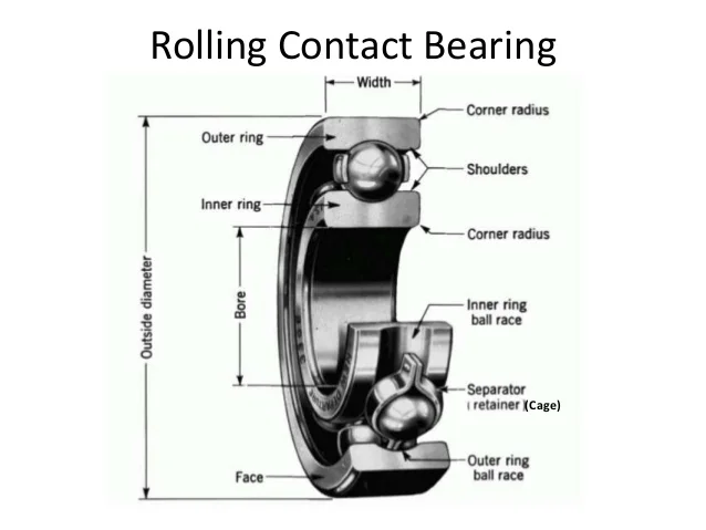
Figure 1: Diagram of Rolling Contact Bearings
Rolling contact bearings are vital components in many mechanical systems, providing efficient support and guidance for rotating shafts. Understanding the various types, load capacities, selection criteria, and lubrication methods is essential for optimizing performance and ensuring the reliability of machinery. By considering these factors in the design and selection process, engineers can significantly enhance the longevity and effectiveness of rolling contact bearings in diverse applications.
Unit 2: Spur Gear
Introduction to Gear Drives
Gear drives are essential mechanical systems used to transmit power and motion between shafts. They consist of interlocking gears that work together to achieve desired speed and torque transformations. The efficiency and effectiveness of gear drives make them critical in various applications, from automotive transmissions to industrial machinery.
Classification of Gears
Gears can be classified based on several criteria, including their shape, arrangement, and application. The primary classifications are:
- Based on the Axis of Rotation:
- Parallel Axis Gears: Such as spur gears and helical gears.
- Non-Parallel Axis Gears: Such as bevel gears and worm gears.
- Based on Tooth Shape:
- Involute Gears: Most common, providing smooth engagement.
- Cycloidal Gears: Used in specific applications for unique advantages.
- Based on Tooth Arrangement:
- Spur Gears: Teeth are parallel to the axis.
- Helical Gears: Teeth are angled, allowing for smoother operation.
Law of Gearing
The law of gearing states that the angular velocity ratio of two gears in mesh must remain constant for the gears to operate smoothly. This is achieved through the proper design of the tooth profiles, which ensures that the points of contact between the gears remain constant during rotation. The primary relationships involved in the law of gearing include:
θ1 / θ2 = N2 / N1
Where:
- θ1 = Angular displacement of gear 1
- θ2 = Angular displacement of gear 2
- N1 = Number of teeth on gear 1
- N2 = Number of teeth on gear 2
Terminology of Spur Gear
Understanding the terminology associated with spur gears is crucial for effective design and analysis. Key terms include:
- Pitch Circle: An imaginary circle where the teeth of two gears effectively engage.
- Base Circle: The circle from which the involute profile of the tooth is generated.
- Addendum: The radial distance from the pitch circle to the top of the teeth.
- Dedendum: The radial distance from the pitch circle to the bottom of the teeth.
- Face Width: The width of the gear tooth in the axial direction.
Standard System of Gear Tooth Force Analysis
Gear tooth forces are critical for determining the performance and safety of gear systems. The analysis includes:
- Normal Force (FN): The force acting perpendicular to the tooth surface.
- Tangential Force (FT): The force acting parallel to the pitch circle, responsible for transmitting torque.
The relationship between these forces can be analyzed using:
FT = T / r
Where:
- T = Torque applied to the gear
- r = Pitch radius of the gear
Gear Tooth Failures
Gear tooth failures can lead to catastrophic machinery breakdowns. Common modes of failure include:
- Tooth Fracture: Caused by excessive loads exceeding the material strength.
- Wear: Progressive material loss due to friction and inadequate lubrication.
- Pitting: Surface fatigue that results in small, craters on the tooth surface.
- Scuffing: Severe adhesive wear resulting from high loads and low lubrication.
Understanding these failure modes is essential for implementing design strategies that enhance durability and reliability.
Selection of Materials
The material selection for gears significantly affects their performance and longevity. Common materials include:
- Steel: Widely used for its strength and toughness; suitable for high-load applications.
- Cast Iron: Offers good wear resistance; commonly used in lower load applications.
- Plastic: Lightweight and corrosion-resistant; suitable for low-load applications where noise reduction is desired.
Factors to consider when selecting materials include load requirements, environmental conditions, and manufacturing processes.
Constructional Features
The design and construction of spur gears involve various parameters, including:
- Number of Teeth: Affects the gear ratio and strength; the number of teeth must be chosen to avoid interference and ensure proper meshing.
- Face Width: The width of the gear tooth, which influences the load-carrying capacity.
Beam Strength Equation
The beam strength equation is used to analyze the bending strength of gear teeth. It is given by:
σb = (M * c) / I
Where:
- σb = Bending stress on the tooth
- M = Moment acting on the tooth
- c = Distance from the neutral axis to the outermost fiber
- I = Moment of inertia of the tooth’s cross-section
This equation helps ensure that the gear teeth are designed to withstand the bending stresses experienced during operation.
Effective Load on Gear Tooth
The effective load on a gear tooth accounts for both the tangential load and any additional factors that influence load distribution, such as misalignment and wear. It can be expressed as:
Peffective = FT + ΔF
Where:
- ΔF = Additional load due to factors like misalignment.
Estimation of Module Based on Beam Strength
The module of a gear, which is a measure of its tooth size, can be estimated based on beam strength requirements. It is defined as:
m = (Ft * K) / (σb * cos(φ))
Where:
- m = Module
- Ft = Tangential force acting on the gear tooth
- K = A factor based on the number of teeth
- σb = Bending stress
- φ = Pressure angle
Design for Maximum Power Capacity
Designing spur gears to handle maximum power capacity involves optimizing the gear dimensions, materials, and lubrication to minimize losses and maximize efficiency. Key considerations include:
- Torque Capacity: Ensuring the gear can handle the required torque without failure.
- Speed Ratings: Determining the maximum allowable speed to prevent excessive wear and overheating.
- Lubrication: Adequate lubrication is essential for minimizing friction and heat generation.
By addressing these factors, engineers can design spur gears that deliver reliable and efficient performance in demanding applications.
Lubrication of Gears
Effective lubrication is critical for the longevity and performance of spur gears. The primary functions of lubrication include:
- Reducing Friction: Lowering the friction between meshing gears to minimize wear and heat generation.
- Cooling: Dissipating heat generated during operation to maintain optimal operating temperatures.
- Contamination Protection: Preventing dirt and debris from entering the gear mechanism.
Common lubrication methods include:
- Grease Lubrication: Ideal for applications where relubrication is infrequent.
- Oil Lubrication: Preferred for high-speed applications, offering superior cooling properties.
Helical Gears
Helical gears are similar to spur gears but feature teeth that are cut at an angle, providing a smoother engagement and the ability to handle higher loads. Key aspects include:
Terminology
Similar to spur gears, helical gears also have specific terminology including:
- Virtual Number of Teeth: The number of teeth that a helical gear appears to have based on its helix angle.
- Tooth Proportions: The relationship between various dimensions of the tooth, affecting strength and performance.
Force Analysis
The force analysis for helical gears involves understanding how the angle of the teeth affects the force distribution and load capacity. The axial load component increases due to the helix angle, which must be considered in design calculations.
Beam Strength Equation
The beam strength equation for helical gears is similar to that of spur gears, but must account for the angle of the helix:
σb = (Mh * c) / Ih
Where:
- Mh = Moment due to helical gear loads
- Ih = Moment of inertia considering the helix angle
Effective Load on Gear Tooth
Similar to spur gears, the effective load on helical gear teeth can be analyzed, with adjustments made for the axial load component due to the helix angle.
Wear Strength Equation
The wear strength of helical gears can be expressed using an equation that considers the tooth geometry, load, and material properties to predict the wear resistance.

Figure 1: Diagram of Spur Gears
Understanding the principles of spur and helical gears is fundamental for mechanical design and engineering. Proper analysis and design considerations—including material selection, lubrication, force analysis, and beam strength equations—are essential for optimizing performance and ensuring reliability in gear applications. By applying these principles, engineers can develop effective gear systems capable of meeting demanding operational requirements.
Unit 3: Bevel Gears and Worm Gears
Bevel Gears
Types of Bevel Gears
Bevel gears are used to transmit power between shafts that are typically at right angles to each other. The main types of bevel gears include:
- Straight Bevel Gears: Teeth are straight and inclined to the gear axis, providing direct engagement.
- Spiral Bevel Gears: Teeth are curved, allowing for smoother engagement and higher load capacities.
- Hypoid Gears: Similar to spiral gears, but the axes do not intersect, enabling a more compact design.
Terminology of Straight Bevel Gears
Understanding the terminology related to straight bevel gears is crucial for effective design and analysis. Key terms include:
- Pitch Cone: The cone that represents the pitch circle of the gear.
- Pitch Angle: The angle between the pitch cone and the axis of the gear.
- Face Width: The width of the gear tooth in the axial direction.
- Tooth Depth: The radial distance from the pitch circle to the tip of the tooth.
Force Analysis
Force analysis for bevel gears involves understanding how the load is distributed along the tooth. The main forces at play include:
- Normal Force (FN): The force acting perpendicular to the tooth surface.
- Tangential Force (FT): The force responsible for torque transmission.
- Axial Force (FA): The force acting along the axis of the gear, significant in spiral bevel gears.
The force relationships can be expressed as:
FT = T / r
Where:
- T = Torque applied to the bevel gear
- r = Pitch radius of the bevel gear
Beam and Wear Strength
The beam strength of bevel gears can be analyzed using similar principles as spur gears. The bending stress can be calculated as:
σb = (M * c) / I
Where:
- M = Moment acting on the tooth
- c = Distance from the neutral axis to the outermost fiber
- I = Moment of inertia of the tooth’s cross-section
For wear strength, the analysis involves evaluating the contact stresses and ensuring they remain below the material limits to prevent surface degradation.
Effective Load on Gear Tooth
The effective load on a bevel gear tooth accounts for both the tangential and axial loads, and can be expressed as:
Peffective = FT + FA
Where:
- FT = Tangential force
- FA = Axial force (for spiral bevel gears)
Worm Gears
Terminology
Worm gears consist of a worm (screw) and a worm wheel (gear), used to achieve high torque and low-speed applications. Key terms include:
- Pitch Diameter: The diameter at which the worm’s teeth engage with the gear.
- Lead: The distance the worm advances in one complete turn.
- Helix Angle: The angle between the axis of the worm and the line of the teeth.
Proportions
The proportions of worm gears affect their performance and efficiency. Important factors include:
- Worm Gear Ratio: The ratio of the number of teeth on the worm wheel to the number of starts on the worm.
- Center Distance: The distance between the centers of the worm and the gear, influencing overall design.
Force Analysis
The force analysis for worm gears involves evaluating the loads transmitted between the worm and the gear. Key considerations include:
- Tangential Load: The load that contributes to torque transmission.
- Radial Load: The load acting perpendicular to the tangential load.
Using vector analysis, the resultant force can be determined, considering both tangential and radial components.
Friction in Worm Gears
Friction plays a significant role in the performance of worm gears. Factors influencing friction include:
- Material Selection: Different materials exhibit varying coefficients of friction.
- Lubrication: Proper lubrication minimizes friction and wear.
- Helix Angle: The angle affects the amount of friction encountered during operation.
Vector Method
The vector method is used to analyze forces in worm gears, where the forces acting on the worm and gear are represented as vectors. This method simplifies calculations related to resultant forces and moments, providing a clearer understanding of the load distribution.
Selection of Materials
Material selection for worm gears is crucial for ensuring durability and performance. Common materials include:
- Bronze: Often used for worm wheels due to its excellent wear resistance.
- Steel: Commonly used for worms due to its strength and hardness.
- Plastic: Suitable for low-load applications where noise reduction is desired.
Strength and Wear Rating
The strength and wear rating of worm gears are essential for ensuring reliability. These ratings are determined based on factors such as:
- Load Capacity: The maximum load the gear can handle without failure.
- Wear Resistance: The ability of the gear to withstand wear over time.
The ratings are typically provided by manufacturers based on standardized testing and can guide engineers in selecting appropriate components for specific applications.
Thermal Considerations
Worm gears can generate significant heat due to friction during operation. Key thermal considerations include:
- Heat Dissipation: Effective cooling methods must be implemented to prevent overheating.
- Lubrication: Adequate lubrication not only reduces friction but also aids in heat dissipation.
- Material Properties: Materials should be selected for their ability to withstand thermal expansion and maintain performance at elevated temperatures.
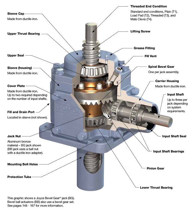
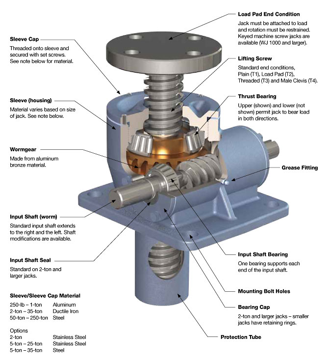
Figures: Diagram of Bevel and Worm Gears
Understanding the principles of bevel and worm gears is essential for effective mechanical design. Proper analysis of forces, material selection, and thermal management are crucial for ensuring reliable performance in gear systems. By applying these principles, engineers can develop gear systems that meet demanding operational requirements while maintaining efficiency and durability.
Unit 4: Belt and Flywheel
Belt Drives
Flat and V Belts
Belts are widely used in mechanical systems to transmit power between rotating shafts. The two common types of belts are:
- Flat Belts: Used for transmitting power over long distances with minimal slippage. They have a rectangular cross-section.
- V Belts: Designed with a trapezoidal cross-section, providing better grip and less slippage, especially in compact arrangements.
Geometric Relationship
The geometric relationship of belt drives is crucial for determining belt lengths and tensions. Key parameters include:
- Pulley Diameter (D): The diameter of the driving and driven pulleys.
- Belt Length (L): The total length of the belt, which can be calculated using the formula:
L = 2C + (π/2)(D1 + D2) + (D1 - D2)² / 4C
Where:
- C = Center distance between the pulleys
- D1 = Diameter of the driving pulley
- D2 = Diameter of the driven pulley
Analysis of Belt Tensions
Analyzing belt tensions is essential for ensuring efficient power transmission. The tension in a belt can be expressed as:
T1 - T2 = (F * L) / R
Where:
- T1 = Tension in the tight side
- T2 = Tension in the slack side
- F = Force acting on the belt
- L = Length of the belt
- R = Radius of the driving pulley
Condition for Maximum Power
The condition for maximum power transmission occurs when the tension ratio is optimized. This can be expressed as:
T1 / T2 = e^(μθ)
Where:
- μ = Coefficient of friction between the belt and pulley
- θ = Angle of wrap in radians
Selection of Flat and V Belts from Manufacturer’s Catalogue
When selecting belts, it is crucial to refer to the manufacturer’s catalogue, which provides data on:
- Belt Specifications: Width, thickness, and length options.
- Load Capacity: Maximum load the belt can handle.
- Speed Ratings: Maximum operating speed.
Adjustment of Belt Tensions
Proper tension adjustment is vital to avoid slippage and ensure efficient operation. The tension can be adjusted by:
- Changing the center distance between pulleys.
- Using tensioning devices or idler pulleys.
- Checking the manufacturer’s recommendations for optimal tension settings.
Roller Chains
Roller chains are another method of power transmission used in various applications. Key aspects include:
- Geometric Relationship: The relationship between the number of teeth on the sprocket and the roller chain links.
- Polygonal Effect: The tendency of the chain to form a polygonal shape when engaged with sprockets, which can affect power transmission efficiency.
Flywheels
Introduction
Flywheels are mechanical devices used to store rotational energy. They help smooth out variations in power delivery, providing consistent energy output in machines. Flywheels are used in various applications, including engines, machinery, and energy storage systems.
Types of Flywheels
The main types of flywheels include:
- Disc Flywheel: A simple disc-shaped flywheel, ideal for storing energy in a rotational form.
- Arm Flywheel: A flywheel with arms extending outward, providing a larger moment of inertia for energy storage.
Stresses in Disc and Arm Flywheels
Understanding stresses in flywheels is crucial for safe and effective design. Key considerations include:
- Radial Stresses: Due to centrifugal forces acting on the flywheel.
- Circumferential Stresses: Caused by the rotational motion of the flywheel.
The maximum stress can be calculated using the formula:
σ = (ρ * ω² * r²) / 2
Where:
- σ = Maximum stress
- ρ = Density of the flywheel material
- ω = Angular velocity
- r = Radius of the flywheel
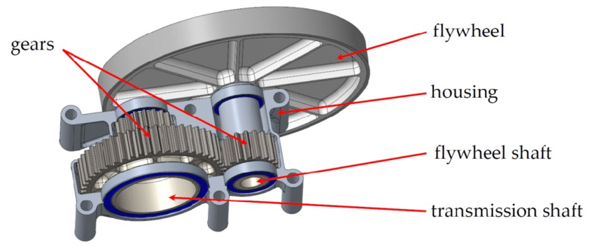
Figure 1: Diagram of Belt Drives and Flywheels
Understanding the mechanics of belt drives and flywheels is essential for effective power transmission in mechanical systems. By analyzing belt tensions, selecting appropriate components, and understanding the principles of flywheel operation, engineers can design efficient and reliable mechanical systems.
Unit 5: Brakes and Clutches
Clutches
Introduction to Clutches
Clutches are mechanical devices that connect and disconnect power transmission between two rotating shafts. They allow the driver to engage or disengage the engine from the transmission, facilitating smooth acceleration and deceleration in vehicles. Understanding the different types of clutches is essential for designing efficient mechanical systems.
Types of Clutches
Clutches are classified based on their operation, design, and application. The main types include:
- Single Plate Clutch: Typically used in automobiles, this clutch consists of a single friction disc that engages with the flywheel. It is simple, compact, and widely used due to its efficiency.
- Multi-Plate Clutch: This clutch uses multiple friction plates stacked together to increase torque capacity while maintaining a smaller overall size. It is often used in high-performance vehicles and motorcycles.
- Cone Clutch: Featuring a conical surface, this clutch engages by sliding the cone into the flywheel. It is suitable for high-speed applications and can handle higher torque loads.
- Centrifugal Clutch: Automatically engages when the engine speed reaches a certain threshold, using centrifugal force. Commonly found in lawn mowers and small engines.
- Hydraulic Clutch: Uses hydraulic fluid to transmit force, providing smoother engagement and disengagement. Common in modern vehicles with automatic transmissions.
Torque Capacity
The torque capacity of a clutch is a critical factor that determines its performance. It is defined by the friction material, contact area, and applied force. The formula for calculating torque capacity is:
T = μ * N * r
Where:
- T = Torque capacity (Nm)
- μ = Coefficient of friction between the clutch plates
- N = Normal force applied on the clutch plates (N)
- r = Effective radius at which the force is applied (m)
Higher torque capacity allows for better performance, especially in applications requiring rapid acceleration or high load conditions.
Friction Materials
The choice of friction materials in clutches is essential for effective power transmission and durability. Common materials include:
- Organic Materials: Typically made from resins and fibers, they offer good friction performance but may wear out faster under high temperatures.
- Ceramic Materials: Provide excellent heat resistance and durability, suitable for high-performance applications.
- Metallic Materials: Often used in high-torque applications due to their durability, but can generate higher wear rates.
- Composite Materials: Combine different materials to optimize performance, offering a balance between friction and wear resistance.
Brakes
Introduction to Brakes
Brakes are mechanical devices used to slow down or stop the motion of a vehicle or machinery. They convert kinetic energy into heat energy through friction, allowing for controlled deceleration. Understanding the types and functionalities of brakes is crucial for engineering safe and effective systems.
Types of Brakes
The main types of brakes include:
- Block with Shoe Brake: This brake consists of a shoe that presses against a rotating drum, creating friction to slow down the motion. It is widely used in vehicles and machinery.
- Pivoted Brake with Long Shoe: Features a long shoe that pivots to engage the drum. This design allows for greater surface area contact, resulting in increased stopping power.
- Internal Expanding Shoe Brake: Utilizes a pair of shoes that expand against the inner surface of a drum when activated, providing efficient braking action.
- Disc Brakes: Utilize a rotating disc and calipers that apply friction pads against the disc to slow down the vehicle. Known for better heat dissipation and performance.
- Hydraulic Brakes: Use hydraulic fluid to transfer force from the brake pedal to the brake pads, providing greater stopping power with less effort.
Energy Equation
The energy absorbed by the brake system can be calculated using the work-energy principle, which states that the work done by the brake is equal to the energy lost by the vehicle’s kinetic energy. The basic equation is:
W = F * d
Where:
- W = Work done by the brake (energy absorbed, in joules)
- F = Friction force applied by the brake (in newtons)
- d = Distance over which the force is applied (in meters)
Understanding this equation helps engineers design braking systems that can effectively dissipate energy and provide adequate stopping power.
Thermal Considerations
Braking generates significant heat, which can lead to performance degradation and component failure if not managed properly. Key considerations include:
- Heat Dissipation: Effective design is necessary to dissipate heat generated during braking. This can be achieved through vented discs or additional cooling systems.
- Material Properties: Brake materials must withstand high temperatures without losing their frictional properties. The choice of materials impacts braking efficiency and safety.
- Brake Fade: A reduction in braking performance due to overheating, resulting in decreased friction. Engineers must design systems to minimize this risk.
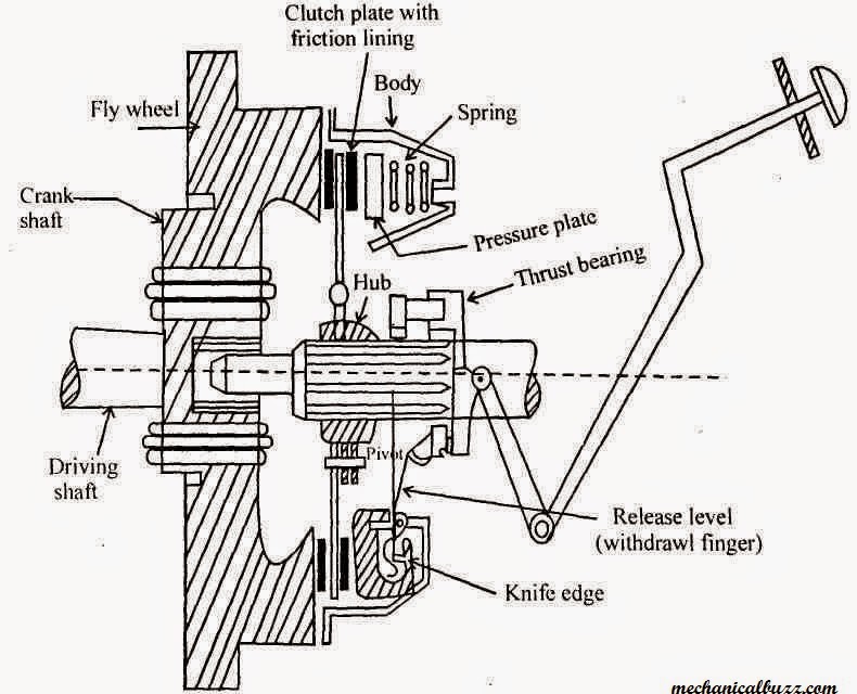
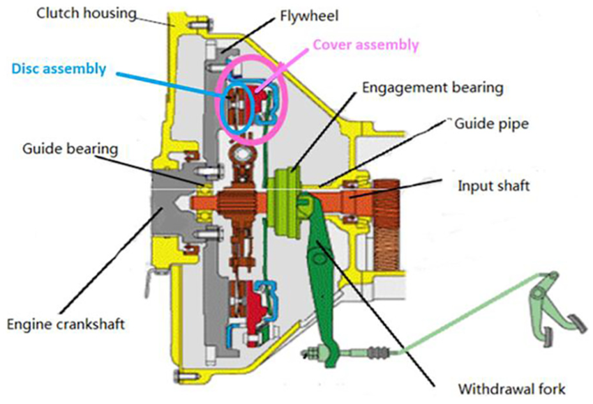
Figure 1: Diagram of Brakes and Clutches showing various types and their mechanisms.
Understanding the principles of brakes and clutches is vital for designing reliable mechanical systems. By analyzing the different types, torque capacities, friction materials, and thermal considerations, engineers can develop efficient power transmission solutions that meet operational demands. Proper selection and design of braking and clutch systems ensure safety and performance in various applications.
Texts:
- V. B. Bhandari, “Design of Machine Elements”, Tata McGraw Hill Publications, New Delhi, 1998.
- R. L. Norton, “Machine Design: An Integrated Approach”, Pearson Education.
References:
- J.E. Shigley, C. Mischke, “Mechanical Engineering Design”, Tata McGraw Hill Inc, New York, 6th edition, 2003.
- R. C. Juvinall, K. M. Marshek, “Fundamentals of Machine Component Design”, John Wiley & Sons, Inc, New York, 2002.
