Unit 1: Mechanical Engineering Design Process
1. Traditional Design Methods
Traditional design methods are based on empirical knowledge and established practices. They involve a sequence of steps including problem identification, conceptual design, detailed design, and prototype testing. These methods often rely on experience and historical data.

2. General Industrial Design Procedure
The general industrial design procedure consists of:
- Problem Definition: Identifying the needs and requirements.
- Conceptual Design: Developing initial design ideas and concepts.
- Detailed Design: Creating detailed plans and specifications.
- Prototyping: Building and testing prototypes.
- Production: Finalizing the design for mass production.
- Feedback and Improvement: Analyzing performance and making necessary adjustments.
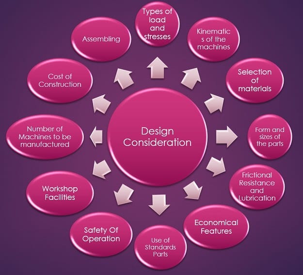
3. Design Considerations
Design considerations are factors that influence the design process, including:
- Functionality: How well the design performs its intended function.
- Safety: Ensuring the design is safe for users and operators.
- Cost: Managing the costs of materials, production, and maintenance.
- Material Selection: Choosing appropriate materials for durability and performance.
- Manufacturability: Ensuring the design can be efficiently manufactured.
4. Phases in Design
The design process is typically divided into the following phases:
- Concept Phase: Generating ideas and selecting the best concept.
- Design Phase: Detailed development of the selected concept.
- Implementation Phase: Building prototypes and preparing for production.
- Evaluation Phase: Testing and evaluating the design performance.
- Production Phase: Manufacturing and delivering the final product.
5. Creativity in Design
Creativity in design involves thinking outside the box to generate innovative solutions. Techniques to enhance creativity include brainstorming, sketching, and using creative problem-solving methods.
6. Use of Standardization
Standardization ensures consistency and compatibility in design. It involves using standardized components, materials, and processes to improve efficiency and reduce costs.
- Standards Organizations: Such as ISO, ANSI, and DIN.
- Benefits: Reduces variability, improves quality, and facilitates international trade.
7. Preferred Series
Preferred series are standard sizes and dimensions used to simplify the design process. Examples include the preferred number series for resistors and capacitors.
8. Introduction to ISO 9000
ISO 9000 is a set of international standards for quality management. It provides guidelines for establishing and maintaining a quality management system (QMS) to ensure that products and services consistently meet customer requirements.
- ISO 9001: Specifies requirements for a QMS.
- ISO 9004: Provides guidance for improving QMS.
9. Use of Design Data Book
A design data book contains standard data and reference materials used in the design process. It includes material properties, design formulas, and engineering standards.
- Applications: Helps in quick reference and standardization.
- Examples: Material strength data, thermal properties, etc.
10. Aesthetic and Ergonomic Considerations in Design
Aesthetic considerations focus on the appearance and visual appeal of the design, while ergonomic considerations ensure that the design is user-friendly and comfortable.
- Aesthetics: Design should be visually pleasing and aligned with user preferences.
- Ergonomics: Design should enhance user comfort and efficiency, minimizing strain and discomfort.
Unit 2: Design of Machine Elements Against Static Loading
1. Theories of Failure
Machine elements are subjected to various loads and stresses during their operation. To ensure safety and avoid failure, engineers use failure theories to predict whether a material will yield or fracture under static loading conditions.
1.1 Maximum Normal Stress Theory (Rankine’s Theory)
This theory states that failure occurs when the maximum normal stress in the material reaches the ultimate tensile strength. It is suitable for brittle materials like cast iron.
Limitations: It does not consider shear stress and is mainly used for brittle materials.
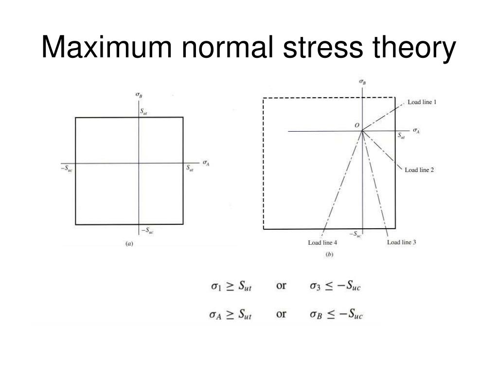
Figure 1: Maximum Normal Stress Theory
1.2 Maximum Shear Stress Theory (Tresca’s Theory)
This theory, also known as Tresca’s criterion, is based on shear stress. It states that failure occurs when the maximum shear stress in a material reaches the shear yield stress.
This theory is more suitable for ductile materials like steel, which fail due to shear rather than direct tension.
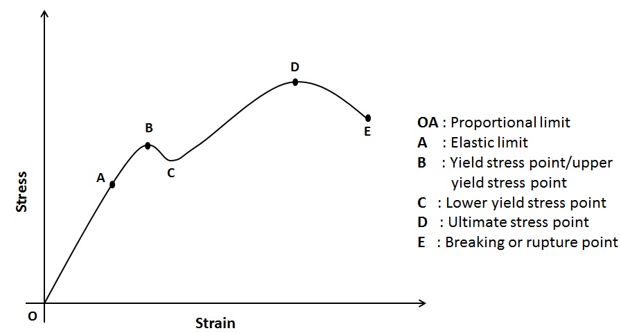
Figure 2: Maximum Shear Stress Theory
1.3 Maximum Distortion Energy Theory (von Mises Theory)
Also known as von Mises’ criterion, this theory suggests that failure occurs when the distortion energy in the material exceeds the energy at yield. It is the most accurate for ductile materials and accounts for combined stresses.
This theory provides more accurate predictions for materials subjected to complex loading conditions.
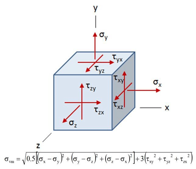
Figure 3: Maximum Distortion Energy Theory
2. Comparison of Various Theories of Failure
Each failure theory has its applications depending on the material type and loading conditions:
- Maximum Normal Stress Theory: Best suited for brittle materials where failure occurs due to tensile stress.
- Maximum Shear Stress Theory: Used for ductile materials that fail due to shear stress.
- Maximum Distortion Energy Theory: Provides accurate results for ductile materials under complex loading conditions.
The von Mises theory is preferred in most modern designs due to its ability to handle multi-axial stress conditions effectively.
3. Direct Loading and Combined Loading
Direct Loading: This occurs when a machine element is subjected to a single type of load, such as pure tension or compression. In such cases, the stress distribution is straightforward and uniform.
Where:
- σ = Stress
- F = Force
- A = Cross-sectional area
Combined Loading: Combined loading involves more than one type of load, such as bending, torsion, or axial force applied simultaneously. The resulting stresses need to be analyzed using failure theories to ensure the safety of the design.
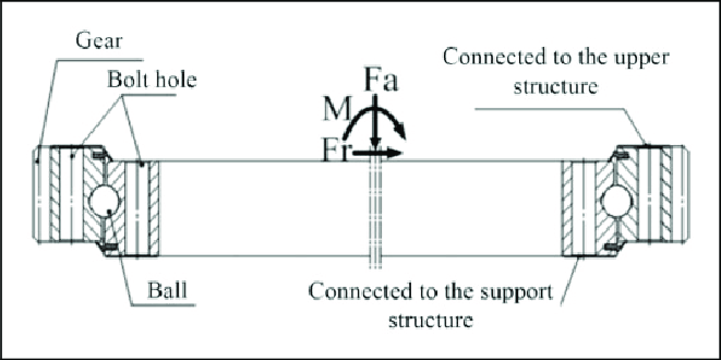
Figure 4: Direct and Combined Loading
4. Joints Subjected to Static Loading
Joints are commonly used in mechanical systems to connect different parts. Some joints are subjected to static loading, meaning that the load does not change over time. Two common examples of such joints are the cotter joint and the knuckle joint.
4.1 Cotter Joint
A cotter joint is used to connect two co-axial rods that are subjected to tensile or compressive forces. It consists of a flat cotter pin that is inserted through both rods to hold them together.
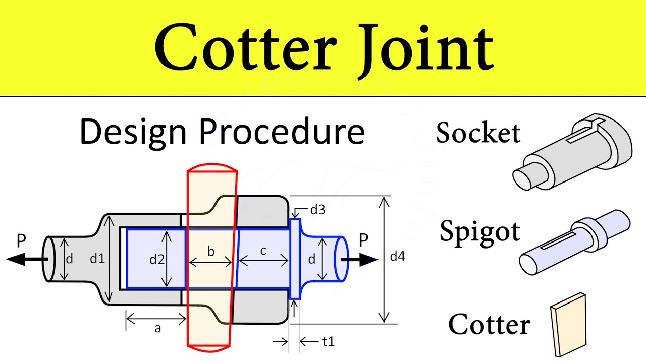
Figure 5: Cotter Joint
4.2 Knuckle Joint
A knuckle joint is used to connect two rods that are under tension or compression but are not aligned co-axially. The joint allows a small amount of angular movement between the rods.
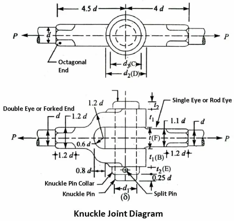
Figure 6: Knuckle Joint
Unit 3: Design Against Fluctuating Loads
1. Stress Concentration
Stress concentration refers to the increase in stress around geometric discontinuities such as holes, notches, or abrupt changes in cross-section. These areas experience higher stress than the surrounding material.
Stress Concentration Factor (Kt): This factor quantifies how much the stress is amplified due to the discontinuity.
Where:
- σmax = Maximum stress at the discontinuity
- Kt = Stress concentration factor
- σnom = Nominal stress (average stress)
Figure 1: Stress Concentration around a Hole
2. Fluctuating Stresses
Fluctuating stresses are variations in stress that occur over time, such as those experienced by components in cyclic loading conditions. These stresses can lead to fatigue failure.
Alternating Stress (σa): The difference between maximum and minimum stress divided by 2.
Mean Stress (σm): The average of maximum and minimum stress.
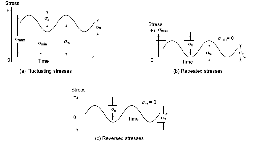
Figure 2: Example of Fluctuating Stresses
3. Fatigue Failure
Fatigue failure occurs when a material fails after repeated loading and unloading cycles. It is characterized by the initiation and growth of cracks due to cyclic stresses.
Endurance Limit: The maximum stress amplitude a material can withstand for an infinite number of cycles without failing.
Materials with high endurance limits are more resistant to fatigue failure.
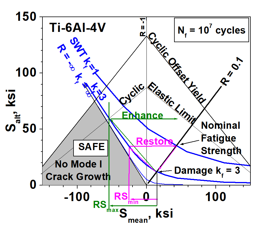
Figure 3: Fatigue Failure Process
4. Notch Sensitivity
Notch sensitivity describes how the presence of notches or sharp corners in a material affects its fatigue strength. Materials with high notch sensitivity experience greater reductions in fatigue strength due to notches.
Notch Sensitivity Factor (q): This factor quantifies the effect of notches on the fatigue strength.
Where:
- σe = Fatigue strength with notches
- σe0 = Fatigue strength without notches
- q = Notch sensitivity factor
- Kt = Stress concentration factor
5. Approximate Estimation of Endurance Limit
Endurance limit can be estimated using empirical relationships based on material properties and stress levels. A common approximation is:
Where:
- σut = Ultimate tensile strength
- σe = Approximate endurance limit
6. Design for Finite Life and Finite Life Under Reversed Stresses
When designing for components with finite life, the goal is to ensure that the component will last for a specific number of cycles. For components subjected to reversed stresses (tension-compression cycles), the fatigue design often involves using the Goodman or Soderberg diagrams to ensure safety.
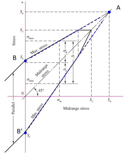
Figure 4: Goodman Diagram for Fatigue Design
7. Cumulative Damage in Fatigue
Cumulative damage theory states that damage caused by repeated loading accumulates over time, leading to failure when the accumulated damage reaches a critical level. The Palmgren-Miner rule is commonly used to estimate cumulative damage.
Where:
- D = Cumulative damage
- ni = Number of cycles at stress level i
- Ni = Number of cycles to failure at stress level i
8. Soderberg and Goodman Diagrams
Soderberg and Goodman diagrams are used to design for fatigue by plotting the allowable stress versus the mean stress to ensure safety under fluctuating loads.
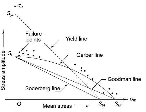
Figure 5: Soderberg Diagram for Fatigue Design
The Goodman diagram is used for materials with a well-defined endurance limit and considers both mean and alternating stresses.
9. Fatigue Design Under Combined Stresses
When a component is subjected to combined stresses, such as bending and axial loads, the design must consider the combined effect on fatigue. Techniques include using equivalent stress concepts and applying the results from Soderberg or Goodman diagrams.
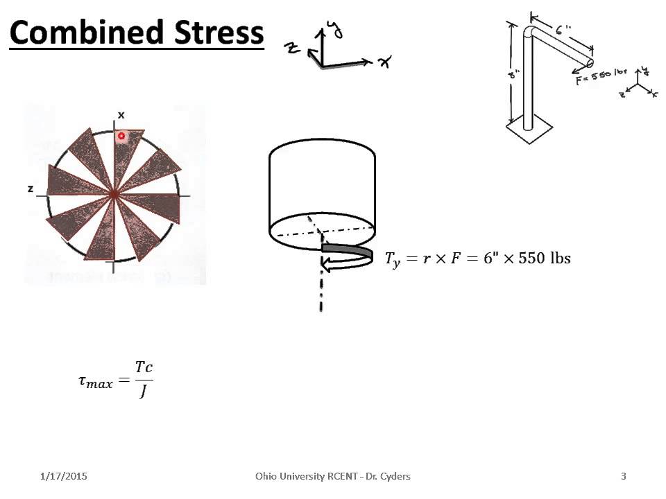
Figure 6: Fatigue Design Under Combined Stresses
Unit 4: Design of Shafts, Keys, and Couplings
1. Design Considerations in Transmission Shafts
Transmission shafts are critical components in mechanical systems, designed to transmit power from one component to another. Key design considerations include:
- Strength: Shafts must withstand various loads without failing. The strength is often evaluated based on material properties and design codes.
- Lateral Rigidity: The shaft should be rigid enough to prevent excessive deflection under load.
- Torsional Rigidity: The shaft must resist twisting under torque without excessive deformation.
- ASME Code: The ASME (American Society of Mechanical Engineers) code provides guidelines for designing transmission shafts to ensure safety and reliability.
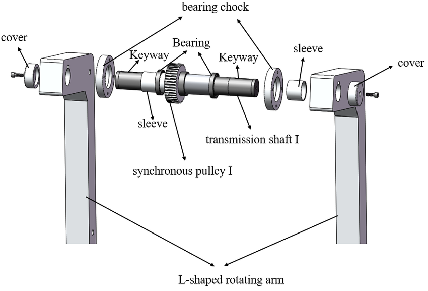
Figure 1: Design Considerations for Transmission Shafts
2. Splined Shafts
A splined shaft is used to connect components while allowing for angular movement. It consists of parallel ridges or teeth that engage with matching grooves in another component.
Design Considerations:
- Load Distribution: Ensure that the load is evenly distributed across the splines to prevent localized stress concentrations.
- Wear Resistance: Use materials and coatings that resist wear and friction.
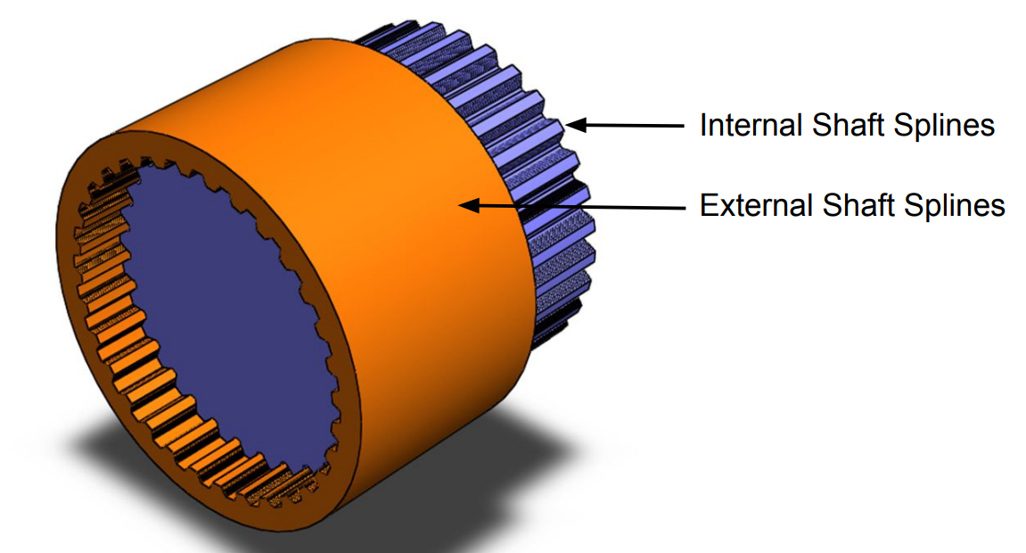
Figure 2: Splined Shaft Design
3. Spindle and Axle Strength
Spindles and axles are shafts that rotate and support loads. Key factors in their design include:
- Material Strength: Use materials that can withstand both bending and torsional loads.
- Fatigue Resistance: Consider fatigue loading conditions to ensure the component has a sufficient fatigue life.
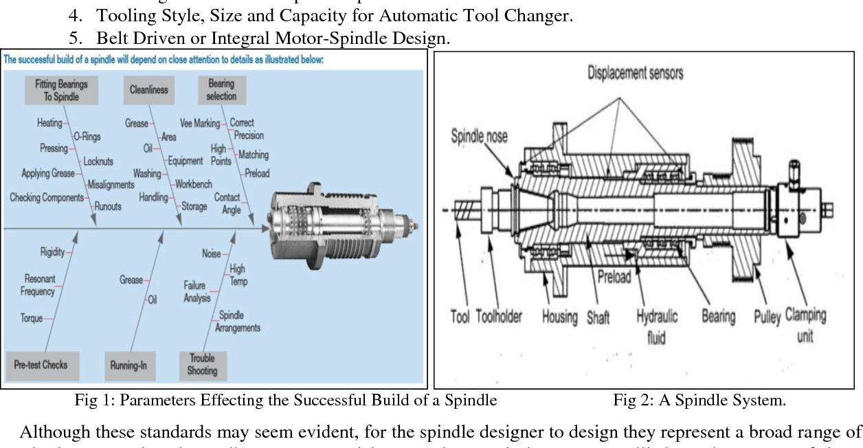
Figure 3: Spindle and Axle Design Considerations
4. Types of Keys
Keys are used to secure rotating components to shafts, preventing relative movement. They come in various types:
4.1 Classification and Fitment in Keyways
Keys can be classified based on their shape and fitment in keyways:
- Straight Keys: Simple rectangular keys inserted into parallel keyways.
- Square Keys: Square cross-section keys used for higher torque applications.
- Woodruff Keys: Semi-circular keys used in applications where axial movement is needed.
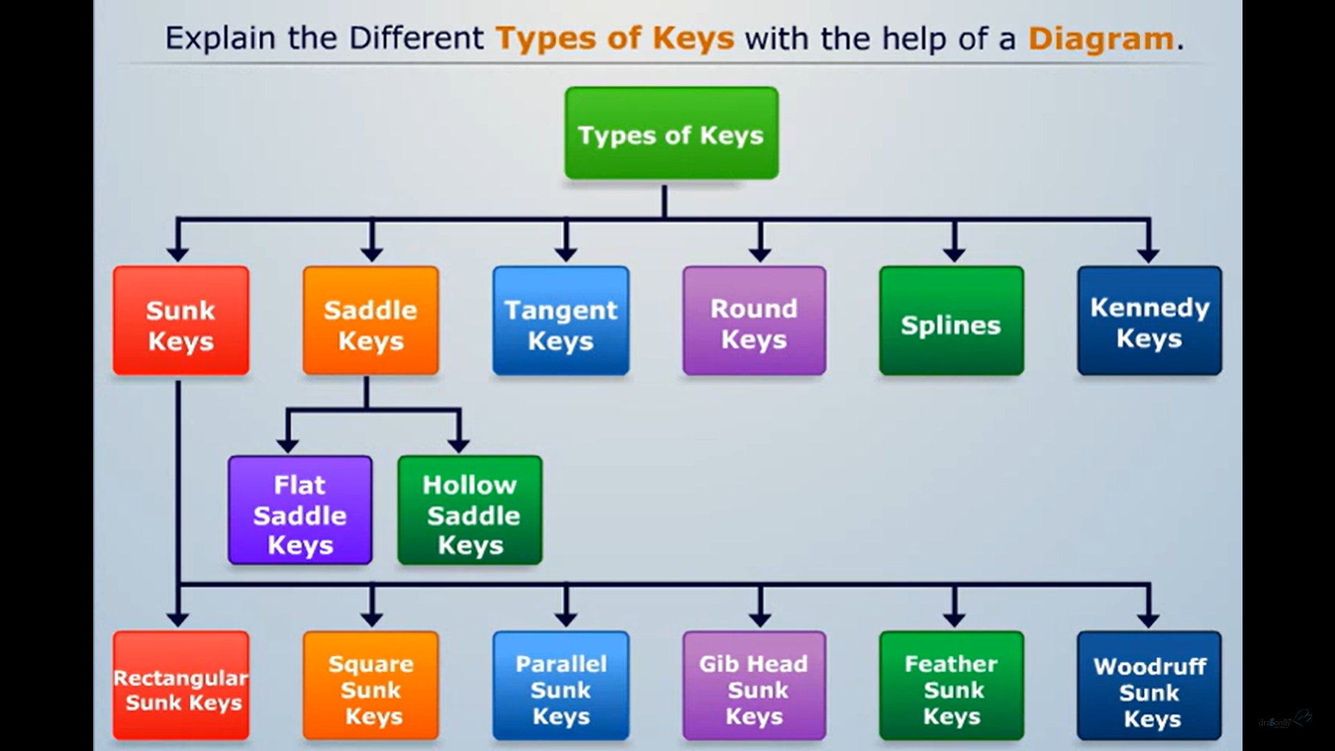
Figure 4: Types of Keys
4.2 Design of Various Types of Keys
Key design involves selecting the appropriate key type and size based on the torque requirements and shaft dimensions:
Where:
- T = Torque
- F = Force applied
- d = Diameter of the shaft
5. Couplings
Couplings connect shafts and transmit torque while allowing for misalignment between components. Key design considerations include:
5.1 Rigid Couplings
Rigid couplings provide a solid connection with no flexibility. They are used when precise alignment is required.
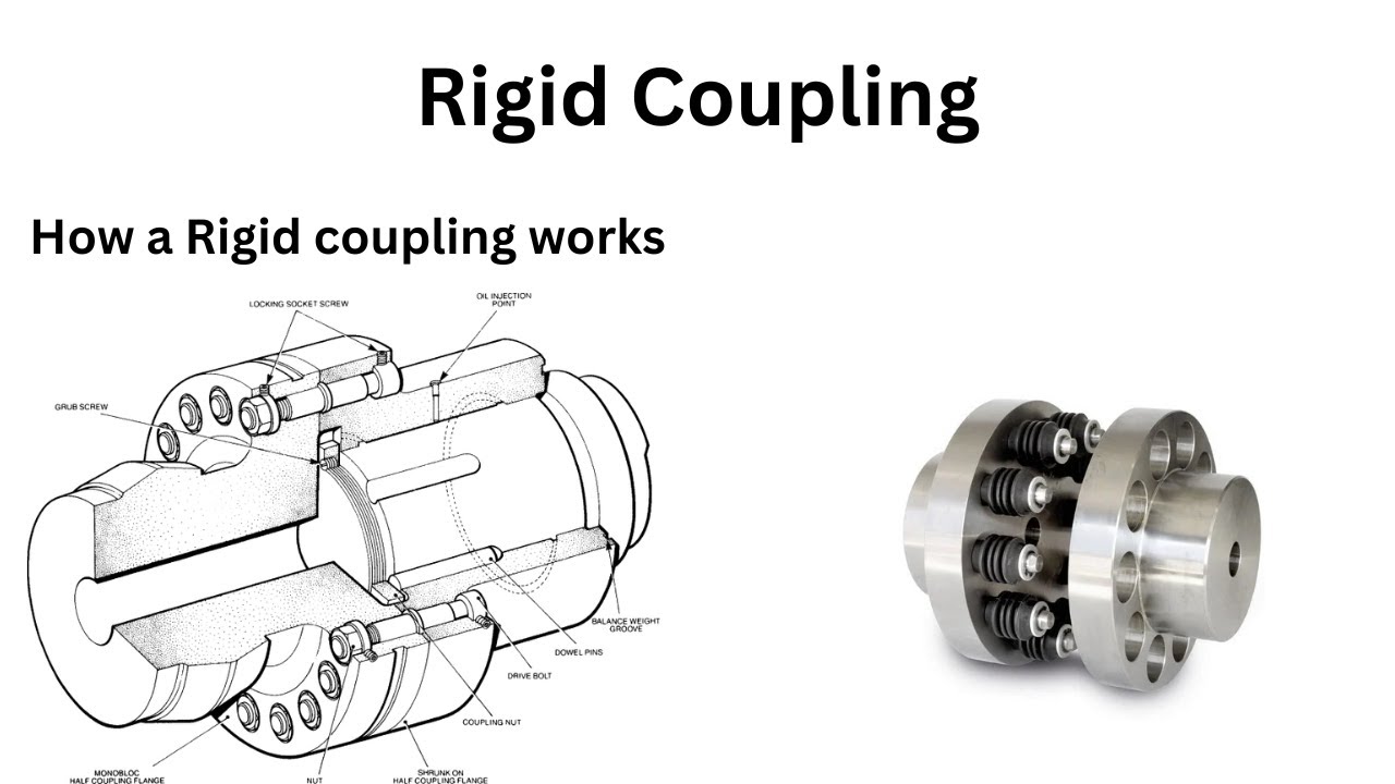
Figure 5: Rigid Coupling Design
5.2 Muff Couplings
Muff couplings are simple cylindrical sleeves that connect shafts. They are used for applications where high torque transmission is required and misalignment is minimal.
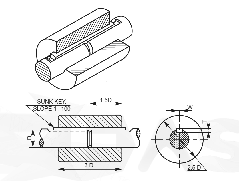
Figure 6: Muff Coupling Design
5.3 Flange Couplings
Flange couplings use flanges bolted together to connect shafts. They are useful for applications requiring disconnection and reconnection.
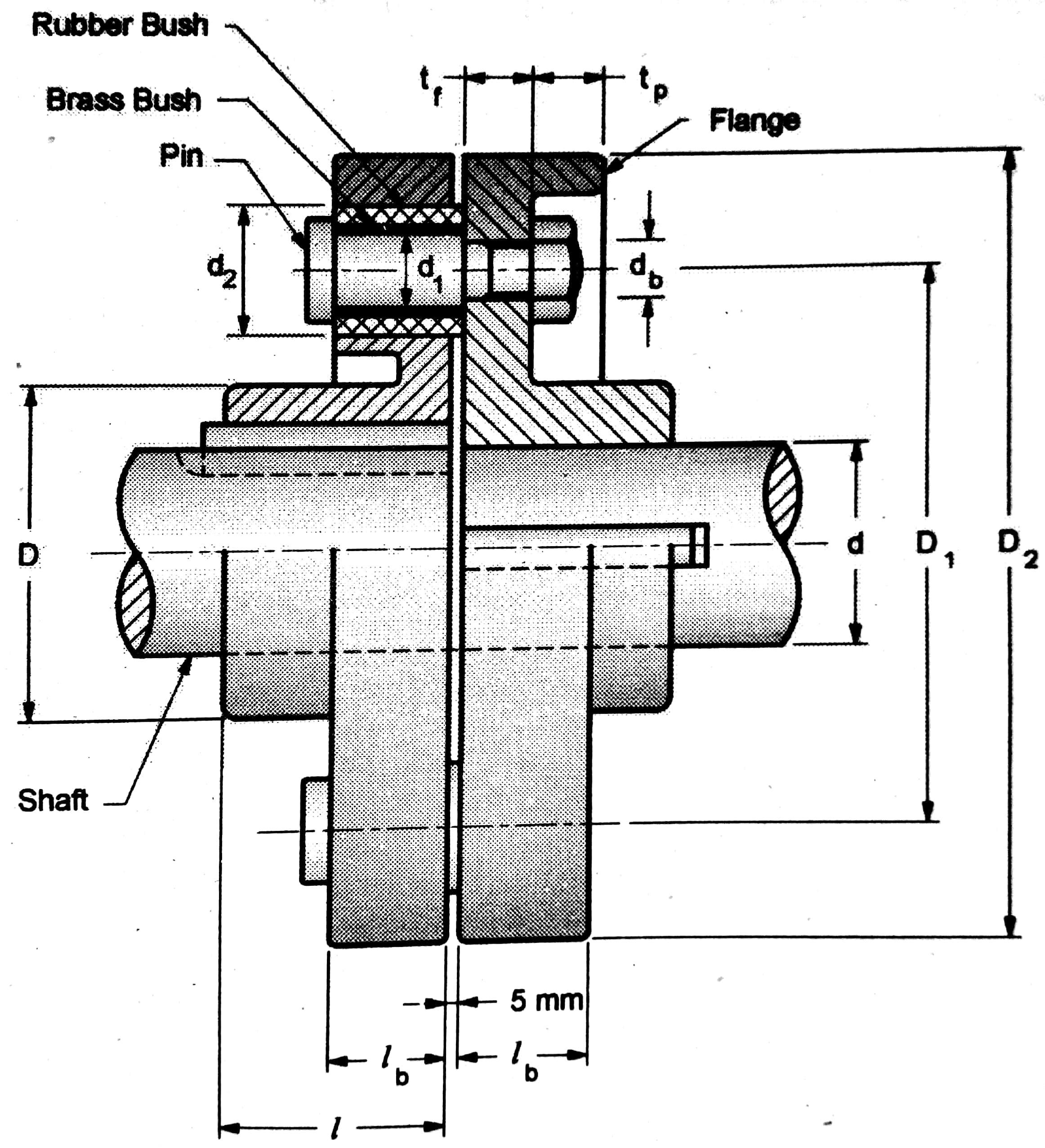
Figure 7: Flange Coupling Design
5.4 Flexible Couplings
Flexible couplings allow for some degree of misalignment and absorb shock loads. They are used in applications with slight misalignments or where vibration damping is needed.
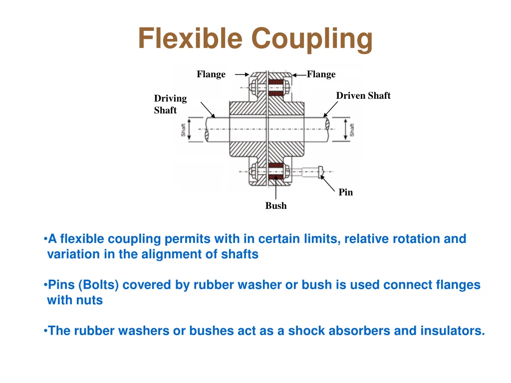
Figure 8: Flexible Coupling Design
Unit 5: Design of Threaded Joints and Mechanical Springs
1. Power Screws
Power screws are mechanical components used to convert rotary motion into linear motion, commonly used in devices like jacks, presses, and lifting mechanisms. The design and functionality of power screws involve several critical aspects:
1.1 Forms of Threads Used for Power Screws and Their Applications
Power screws come in various thread forms, each suited to different applications. The most common types include:
- Square Threads: These are ideal for applications requiring high efficiency, such as in screw jacks and presses. Square threads provide a large contact area, reducing friction and wear.
- Acme Threads: Acme threads balance between strength and ease of manufacture. They are often used in machine tools, where moderate efficiency and durability are required.
- Buttress Threads: These are used in applications where high axial loads are present, such as in clamping devices and power presses.
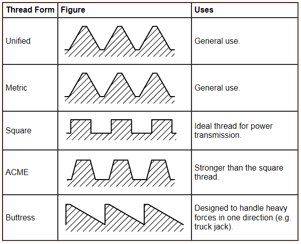
Figure 1: Forms of Threads for Power Screws and Their Applications
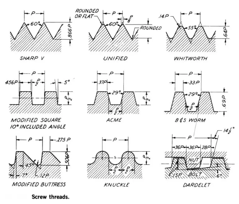
1.2 Torque Analysis for Square Threads
Torque analysis is crucial for determining the forces involved in rotating a power screw. For square threads, the torque required can be calculated using the following formula:
Where:
- T = Torque required
- P = Load on the screw
- d = Diameter of the screw
- φ = Thread angle (typically 90° for square threads)
This formula helps in understanding the mechanical advantage provided by the screw threads and ensures that the torque applied does not exceed the screw’s capacity.
1.3 Efficiency of Screws
The efficiency of a screw is a measure of how effectively it converts rotary motion into linear motion. It can be calculated using the following formula:
Where:
- η = Efficiency
- μ = Coefficient of friction between the screw and the nut
- φ = Thread angle
Higher efficiency means less energy loss due to friction, which is crucial for reducing operational costs and improving performance in applications like screw jacks and presses.
1.4 Self-Locking in Power Screws
A power screw is said to be self-locking if it can hold a load in place without requiring an additional locking mechanism. Self-locking is achieved when:
Where:
- φ = Thread angle
- μ = Coefficient of friction
If the tangent of the thread angle is less than the coefficient of friction, the screw will not backdrive, making it ideal for lifting and clamping applications.
1.5 Stresses in the Power Screw
The stresses in a power screw are critical for ensuring its durability and performance. Key stresses include:
- Shear Stress: This is due to the torque applied to the screw. It can be calculated using:
- Normal Stress: This arises from the axial load. It can be calculated using:
Where:
- τ = Shear stress
- σ = Normal stress
- P = Axial load
- A = Cross-sectional area of the screw
Proper analysis ensures that the power screw can handle the applied loads without failure.
1.6 Design of Screw and Nut
The design of the screw and nut involves selecting appropriate dimensions and materials to achieve the desired performance. Key considerations include:
- Material Selection: Choose materials with high strength and durability to withstand the loads and stresses.
- Thread Design: Ensure the threads are manufactured to the required specifications for optimal performance.
- Nut Design: The nut should match the screw thread profile and be designed to handle the applied loads without excessive wear.
Special types of screws, such as differential and compound screws, and recirculating ball screws, offer advantages in specific applications by improving efficiency and load handling.
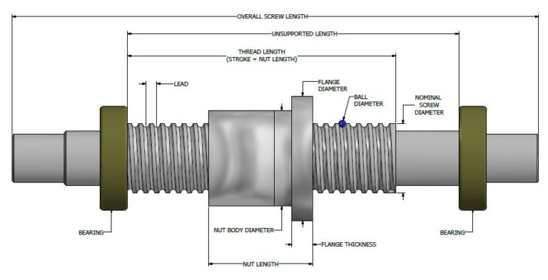
Figure 2: Design of Screw and Nut
2. Welded Joints
Welded joints are crucial for joining metal components in structural and mechanical applications. The design of welded joints involves several key aspects:
2.1 Types of Welded Joints
Welded joints can be categorized based on the configuration of the joining surfaces:
- Butt Welds: Used to join two pieces end-to-end, often in pipes and structural beams.
- Fillet Welds: Used to join two pieces at an angle, commonly used in frames and brackets.
- Edge Welds: Used to join the edges of sheets or plates.
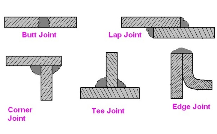
Figure 3: Types of Welded Joints
2.2 Stresses in Butt and Fillet Welds
Welded joints are subjected to various stresses, which can be calculated to ensure structural integrity:
- Shear Stress: The stress experienced along the weld line. It can be calculated using:
- Tensile Stress: Stress experienced parallel to the weld. Calculated using:
Where:
- τ = Shear stress
- σ = Tensile stress
- F = Applied force
- Aw = Weld cross-sectional area
- M = Bending moment
- b = Width of the weld
- h = Height of the weld
Understanding these stresses helps in designing welds that can handle the expected loads without failure.
2.3 Strength of Welded Joints Subjected to Bending Moments
When a welded joint is subjected to bending moments, it is essential to ensure that the joint can withstand the applied forces without failure. The strength can be analyzed using:
Where:
- M = Bending moment
- F = Applied force
- d = Distance from the weld line
Proper design ensures that the welded joint maintains its structural integrity under bending loads.
3. Mechanical Springs
Mechanical springs are used to store and release energy in various applications, including automotive suspensions and machinery. Key aspects of spring design include:
3.1 Stress-Deflection Equation for Helical Springs
The stress in a helical spring is determined by the load applied and the spring’s geometry. The stress-deflection equation is:
Where:
- σ = Shear stress in the spring
- F = Load applied to the spring
- R = Radius of the spring
- d = Diameter of the wire
This equation helps in calculating the stress to ensure that the spring can handle the applied load without failure.
3.2 Wahl’s Factor
Wahl’s factor is used to account for the non-uniform distribution of stress in a helical spring. It is given by:
Where:
- Kw = Wahl’s factor
- d = Diameter of the wire
- R = Radius of the spring
Wahl’s factor is used to modify the stress calculations to account for the effects of curvature and other factors affecting the spring’s performance.
3.3 Styles of Ends
The design of spring ends affects the performance and ease of installation. Common styles include:
- Plain Ends: Simple and economical, but may not provide as stable a seating as other types.
- Closed Ends: Provides better seating and load distribution, often used in applications requiring precise alignment.
- Ground Ends: Ensures the ends of the spring are flat and parallel, providing stable and consistent performance.
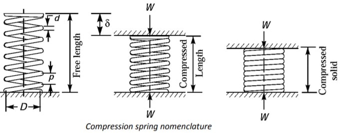
Figure 4: Styles of Spring Ends
3.4 Design of Helical Compression Springs
The design of helical compression springs involves determining the appropriate dimensions and material properties to achieve the desired performance. Key considerations include:
- Spring Constant: Determines how much the spring compresses under a given load.
- Maximum Load: The maximum load the spring can handle without permanent deformation.
- Material Selection: Choose materials with suitable mechanical properties for the intended application.
Designing the spring involves calculating the required wire diameter, coil diameter, and number of coils to meet the performance criteria.
3.5 Shot Peening
Shot peening is a process used to improve the fatigue life of springs by inducing compressive residual stresses on the surface. The process involves:
- Process: Bombarding the surface of the spring with small spherical media (shot) to create compressive stresses.
- Benefits: Enhances fatigue resistance and extends the life of the spring by reducing the likelihood of surface cracks.
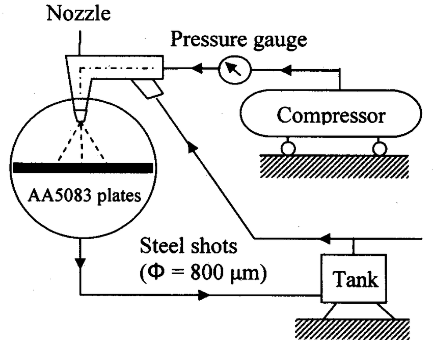
Figure 5: Shot Peening Process
Texts and References
Texts:
- V. B. Bhandari, “Design of Machine Elements”, Tata McGraw Hill Publications, New Delhi, 2008.
- R. L. Norton, “Machine Design: An Integrated Approach”, Pearson Education Singapore, 2001.
References:
- R. C. Juvinall, K. M. Marshek, “Fundamentals of Machine Component Design”, John Wiley & Sons Inc., New York, 3rd edition, 2002.
- B. J. Hamrock, B. Jacobson, and Schmid Sr., “Fundamentals of Machine Elements”, International Edition, New York, 2nd edition, 1999.
- A. S. Hall, A. R. Holowenko, H. G. Langhlin, “Theory and Problems of Machine Design”, Schaum’s Outline Series, Tata McGraw Hill Book Company, New York, 1982.
- J. E. Shigley and C. R. Mischke, “Mechanical Engineering Design”, Tata McGraw Hill Publications, 7th edition, 2004.
- M. F. Spotts, “Design of Machine Elements”, Prentice Hall of India, New Delhi.
