IC-Engine
Unit 1: Fundamentals of Internal Combustion Engines (IC Engines)
Introduction
Internal combustion (IC) engines are mechanical devices that convert chemical energy from fuel into thermal energy, and subsequently into mechanical energy to perform useful work. IC engines are widely used in various applications, including automobiles, power generation, and aircraft. Understanding the fundamentals of IC engines is crucial for mechanical engineers involved in the design and optimization of power systems.
Applications of IC Engines
IC engines have a wide range of applications, including:
- Automobiles: Used in cars, trucks, and motorcycles to power their movement.
- Marine Engineering: Employed in ships, boats, and submarines for propulsion.
- Aviation: Used in airplanes for propelling the aircraft using piston engines.
- Power Generation: IC engines serve as prime movers in generators to produce electricity.
- Heavy Machinery: Used in construction, agricultural, and industrial machinery.
Nomenclature and Engine Components
Key components of an IC engine include:
- Cylinder: The chamber where fuel combustion takes place, leading to piston movement.
- Piston: A cylindrical part that moves up and down within the cylinder to transmit power.
- Crankshaft: Converts the piston’s linear motion into rotational motion.
- Connecting Rod: Connects the piston to the crankshaft and transmits force.
- Camshaft: Controls the opening and closing of valves, timed with piston movement.
- Valves: Intake and exhaust valves regulate the flow of air-fuel mixture and exhaust gases.
- Flywheel: Maintains the momentum of the engine by storing rotational energy.
Engine Classification
IC engines can be classified based on several factors:
- Based on Number of Strokes:
- Two-Stroke Engines: Complete a power cycle in two strokes of the piston (one revolution of the crankshaft).
- Four-Stroke Engines: Complete a power cycle in four strokes of the piston (two revolutions of the crankshaft).
- Based on Fuel Used:
- Petrol (SI) Engines: Spark Ignition engines use petrol as fuel and rely on a spark plug for ignition.
- Diesel (CI) Engines: Compression Ignition engines use diesel fuel and rely on high compression for ignition.
- Based on Cooling System:
- Air-cooled Engines: Use air circulation for cooling.
- Water-cooled Engines: Use water circulation to dissipate heat.
Two-Stroke and Four-Stroke Engines
Two-Stroke Cycle Engines
In a two-stroke engine, the piston completes a power cycle in two strokes:
- Compression Stroke: The piston moves upward, compressing the air-fuel mixture in the cylinder. Near the top of this stroke, ignition occurs.
- Power Stroke: The expanding gases push the piston downwards, producing mechanical work. The exhaust gases are expelled as fresh air-fuel mixture enters the cylinder.
Four-Stroke Cycle Engines
A four-stroke engine completes a power cycle in four distinct strokes:
- Intake Stroke: The piston moves downwards, allowing air-fuel mixture to enter the cylinder through the intake valve.
- Compression Stroke: The piston moves upward, compressing the air-fuel mixture in the cylinder.
- Power Stroke: Ignition occurs, and the piston is pushed down by expanding gases, generating mechanical power.
- Exhaust Stroke: The piston moves upwards again, pushing out exhaust gases through the exhaust valve.
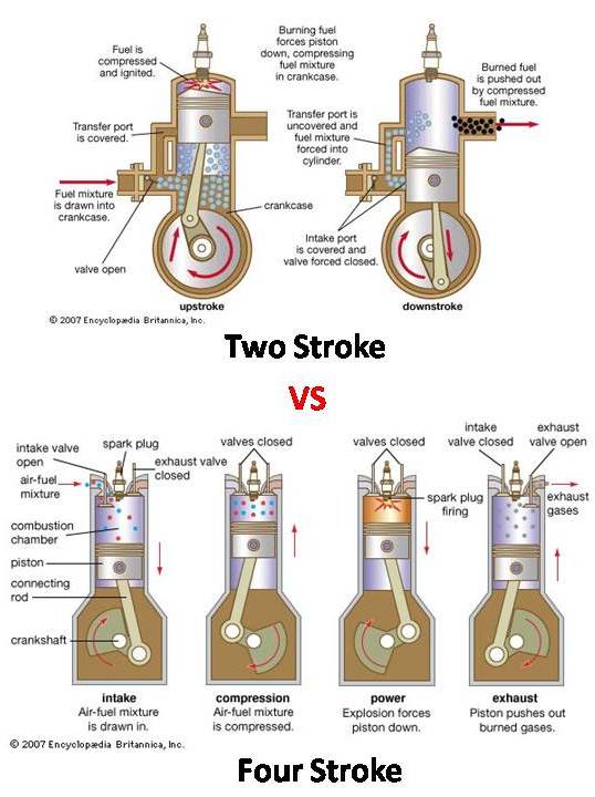
Figure 1: Two-Stroke vs Four-Stroke Engine Cycle
Difference Between SI and CI Engines
The primary difference between Spark Ignition (SI) and Compression Ignition (CI) engines lies in how the fuel is ignited:
- SI Engines: Use petrol as fuel, where the air-fuel mixture is ignited by a spark plug after being compressed.
- CI Engines: Use diesel as fuel, where the air is compressed to a high temperature, and fuel is injected into the hot compressed air, causing ignition.
Valve Timing Diagrams
Valve timing diagrams show the precise timing of the opening and closing of the intake and exhaust valves in relation to the position of the piston. In both two-stroke and four-stroke engines, correct valve timing is critical for optimal engine performance.
For a four-stroke engine, the intake valve opens before the piston reaches Top Dead Center (TDC) on the intake stroke and remains open until after Bottom Dead Center (BDC). The exhaust valve opens before the exhaust stroke starts and closes after the exhaust stroke finishes.
Power Cycles
Air Standard Cycles
Air standard cycles are simplified thermodynamic models used to analyze the ideal performance of IC engines. The key power cycles include:
1. Otto Cycle (Constant Volume Cycle)
The Otto cycle is an idealized thermodynamic cycle that describes the working of a spark-ignition internal combustion engine. It consists of two adiabatic and two constant-volume processes. The efficiency of the Otto cycle depends on the compression ratio.
Processes in the Otto Cycle:
- Adiabatic compression
- Constant-volume heat addition
- Adiabatic expansion
- Constant-volume heat rejection
2. Diesel Cycle (Constant Pressure Cycle)
The Diesel cycle is an idealized cycle for compression-ignition engines where heat is added at constant pressure. It differs from the Otto cycle in that it uses compression ignition rather than spark ignition.
- Adiabatic compression
- Constant-pressure heat addition
- Adiabatic expansion
- Constant-volume heat rejection
3. Dual Cycle
The dual cycle combines features of both Otto and Diesel cycles. It includes constant-volume heat addition followed by constant-pressure heat addition, and is used to model engines that have characteristics of both SI and CI engines.
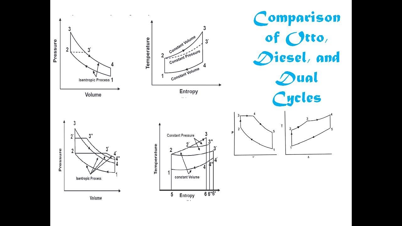
Figure 2: Comparison of Otto, Diesel, and Dual Cycles
Fuel-Air Cycles
Fuel-air cycles take into account the variations in specific heats, the composition of the working fluid, and the actual combustion process. In contrast to ideal air-standard cycles, fuel-air cycles provide a more realistic analysis of IC engine performance. Deviations from ideal cycles are due to factors such as incomplete combustion, heat losses, and the presence of residual gases.
Deviation of Actual Cycles from Ideal Cycles
The actual working cycles of IC engines differ from the ideal air-standard cycles due to several factors, including:
- Heat losses through the cylinder walls.
- Frictional losses in engine components.
- Non-instantaneous combustion.
- Inlet and exhaust valve timing limitations.
- Irregularities in fuel-air mixture and combustion process.
Note: Understanding the deviation of actual cycles from ideal cycles helps engineers optimize the performance and efficiency of IC engines in real-world applications.
Unit 2: Combustion in Engines
Introduction
Combustion is a fundamental process in internal combustion engines (IC engines) where fuel is burned to produce mechanical energy. Understanding combustion is crucial for improving engine efficiency and reducing emissions.
Important Qualities and Ratings of SI Engine Fuels
The performance of Spark Ignition (SI) engines relies heavily on fuel quality. Here are some key qualities:
- Octane Number (ON): Indicates a fuel’s resistance to knocking. A higher octane number means better performance.
- Volatility: Fuels should vaporize easily to mix well with air, affecting combustion efficiency.
- Ignition Quality: Fuels must ignite smoothly with a spark, promoting stable combustion.
Important Qualities and Ratings of CI Engine Fuels
Compression Ignition (CI) engines depend on the auto-ignition of fuel. Key qualities include:
- Cetane Number (CN): Reflects a fuel’s ability to ignite spontaneously. Higher cetane numbers lead to smoother combustion.
- Viscosity: Fuels must flow easily and atomize well for efficient combustion.
- Calorific Value: Measures the heat released during combustion, affecting overall engine efficiency.
Combustion in S.I. Engines
Flame Speed
Flame speed is the rate at which the combustion front moves through the air-fuel mixture. It significantly impacts combustion efficiency and engine performance.
Flame Speed = Distance of Flame Front / Time
Ignition Delay
Ignition delay is the time between the spark plug firing and the actual start of combustion. Shorter ignition delays result in smoother engine operation.
Normal and Abnormal Combustion
- Normal Combustion: The air-fuel mixture ignites in a controlled manner, ensuring smooth power delivery.
- Abnormal Combustion (Knock): Occurs when parts of the air-fuel mixture ignite prematurely, causing pressure spikes that can damage the engine.
Effect of Engine Variables on Flame Propagation and Ignition Delay
- Compression Ratio: Higher ratios increase temperature and pressure, reducing ignition delay.
- Engine Speed: Higher speeds can increase flame propagation but may reduce ignition delay due to less time for heat transfer.
- Fuel Mixture: Lean mixtures (lower fuel-to-air ratios) burn slower than rich mixtures.

Figure 1: Combustion process in an SI Engine
Combustion in C.I. Engines
Combustion of a Fuel Drop
In CI engines, fuel is injected as tiny droplets into high-temperature air. The process includes:
- Ignition Delay: The time between fuel injection and combustion initiation.
- Flame Propagation: Rapid burning of the fuel-air mixture occurs post-ignition.
- Combustion Completion: Remaining fuel burns, concluding the combustion process.
Stages of Combustion in C.I. Engines
- Ignition Delay Period: A critical time frame; shorter delays are preferred to avoid knocking.
- Rapid Combustion: Following ignition, a steep pressure rise occurs.
- Controlled Combustion: The fuel continues burning at a regulated rate, stabilizing pressure.
- Afterburning: Any remaining fuel completes combustion in this final stage.
Combustion Knock
Knock in CI engines results from rapid combustion after ignition delay, leading to damaging pressure fluctuations and noise.
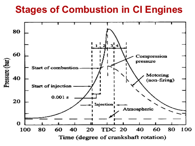
Figure 2: Stages of Combustion in a CI Engine
Types of SI and CI Engine Combustion Chambers
The design of combustion chambers affects combustion efficiency and knock occurrence. Various geometries are employed in engine designs:
SI Engine Combustion Chambers
- Hemispherical Chamber: Offers high efficiency and allows for higher compression ratios.
- Pent-Roof Chamber: Enhances air-fuel mixing and flame propagation.
- Wedge Chamber: Compact and effective for improving flame speed.
CI Engine Combustion Chambers
- Direct Injection Chamber: Injects fuel directly into the combustion chamber, promoting quicker ignition and reduced knocking.
- Indirect Injection Chamber: Fuel is injected into a pre-combustion chamber, resulting in smoother operation and quieter combustion.
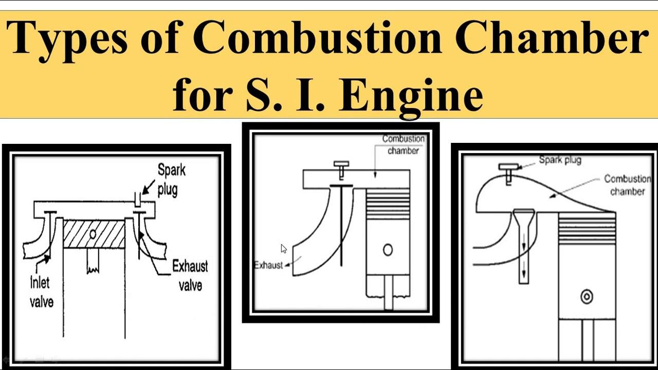
Figure 3: Different types of combustion chambers in SI and CI Engines
Key Formulas for Combustion in Engines
- Heat Release Rate (Q):
Q = mf × CV
Where:
mf = mass of fuel
CV = calorific value of fuel - Thermal Efficiency (ηth):
ηth = Wout / Qin
Where:
Wout = work output
Qin = heat input - Octane Number (ON):
ON = % Iso-Octane / % Heptane
- Cetane Number (CN):
CN = % n-Cetane / % Iso-Cetane
Unit 3: Various Engine Systems and Engine Testing and Performance
Engine Systems
Starting Systems
The starting system is crucial for initiating engine operation. It typically consists of the starter motor, battery, and ignition switch. The motor turns the engine’s flywheel, enabling the engine to start.
Fuel Supply Systems
Fuel supply systems ensure the correct amount of fuel reaches the engine. They include fuel tanks, fuel pumps, fuel filters, and carburetors or fuel injectors. Proper atomization and mixing with air are essential for optimal combustion.
Engine Cooling System
Cooling systems maintain optimal engine temperatures, preventing overheating. They generally consist of:
- Radiator: Cools the engine coolant.
- Water Pump: Circulates coolant through the engine.
- Thermostat: Regulates coolant flow based on temperature.
Ignition System
The ignition system ignites the air-fuel mixture in SI engines. Key components include:
- Spark Plug: Creates a spark to ignite the mixture.
- Ignition Coil: Converts battery voltage to a higher voltage.
- Distributor: Directs high voltage to the correct cylinder.
Engine Friction and Lubrication Systems
Proper lubrication reduces friction and wear in engine components. Lubrication systems can be:
- Pressure Lubrication: Oil is pumped to critical areas.
- Splash Lubrication: Components dip into oil for lubrication.
Friction loss can be calculated using the formula:
Friction Loss = μ × N
Where:
- μ = Coefficient of friction
- N = Normal force
Governing Systems
Governing systems regulate engine speed and power output. They adjust fuel flow and ignition timing based on load conditions, ensuring stable operation under varying demands.
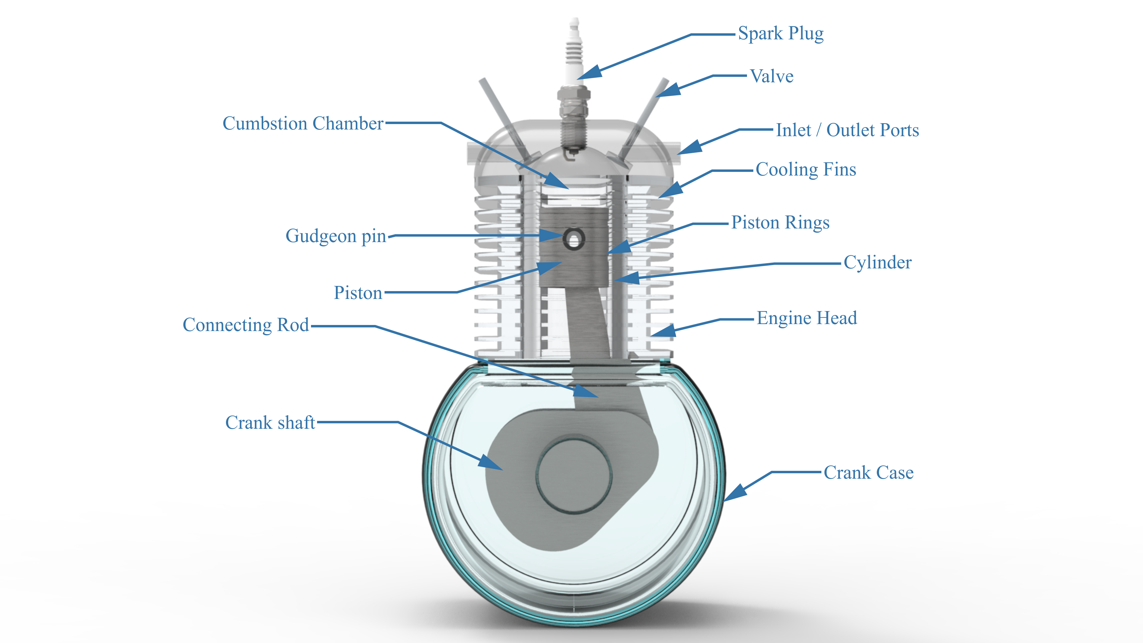
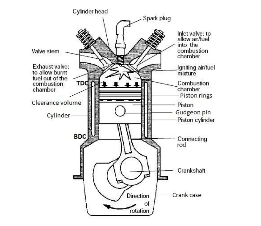
Figure : Overview of Engine Systems
Engine Testing and Performance
Parameters of Engine Testing
Testing parameters include:
- Power Output: The work done by the engine over time, measured in horsepower or kilowatts.
- Torque: The rotational force produced by the engine.
- Fuel Efficiency: The distance traveled per unit of fuel consumed (e.g., km/l or mpg).
Types of Tests and Characteristic Curves
Common engine tests include:
- Performance Testing: Measures engine power, torque, and efficiency.
- Emissions Testing: Assesses pollutant output to ensure compliance with regulations.
- Durability Testing: Evaluates engine lifespan under various conditions.
Characteristic curves, such as power vs. RPM and torque vs. RPM, are essential for understanding engine performance.
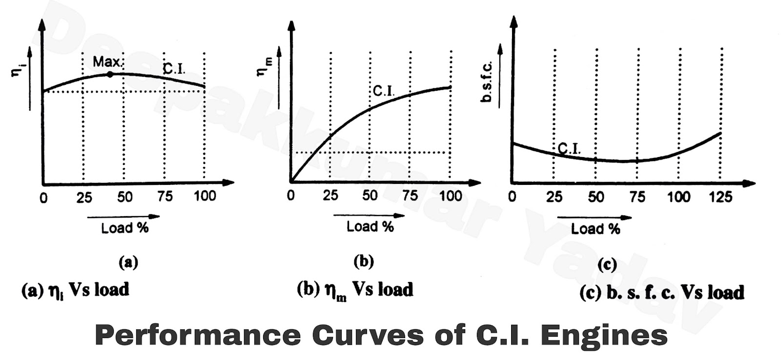
Figure 2: Engine Performance Characteristic Curves
Supercharging in IC Engines
Effect of Attitude on Power Output
The altitude affects engine performance due to changes in air density. At higher altitudes, air is less dense, which can lead to a decrease in power output. Supercharging compensates for this by forcing more air into the combustion chamber.
Types of Supercharging
- Mechanical Supercharging: Uses a belt-driven compressor to increase air intake.
- Turbosupercharging: Utilizes exhaust gases to spin a turbine, which compresses intake air.
Engine Emissions and Control
Pollutants from SI and CI Engines
Common pollutants include:
- Carbon Monoxide (CO): Produced from incomplete combustion.
- Hydrocarbons (HC): Result from unburned fuel.
- Nitrogen Oxides (NOx): Formed at high temperatures during combustion.
Emission Regulations
Various emission regulations have been established to control pollutants, including:
- Bharat Stage (BS): Indian standards for vehicular emissions.
- Euro Standards: European regulations to reduce vehicle emissions.
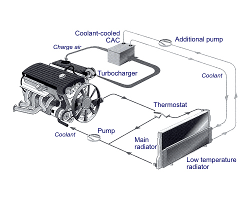
Figure 3: Engine Emission Control Techniques
Unit 4: Alternate Fuels
Introduction
The increasing demand for energy, coupled with environmental concerns associated with fossil fuel consumption, has necessitated the exploration of alternative fuels. These fuels can be derived from renewable resources and can significantly reduce greenhouse gas emissions. This unit will cover the need for alternative fuels, their applications, and the various types of alternative fuels currently in use.
Need for Alternative Fuels
The reliance on conventional fossil fuels has led to several pressing issues, including:
- Environmental Impact: Fossil fuels contribute to air pollution and climate change through the emission of carbon dioxide (CO2) and other harmful pollutants.
- Resource Depletion: The finite nature of fossil fuels raises concerns over their long-term availability.
- Energy Security: Dependency on imported oil can compromise national security and economic stability.
- Technological Innovation: The development of alternative fuels drives advancements in energy technology and sustainable practices.
Applications of Alternative Fuels
Alternative fuels can be utilized across various sectors, including:
- Transportation: Used in vehicles, buses, and trains to reduce emissions.
- Industrial: Powers machinery and equipment in manufacturing processes.
- Residential: Heating and cooking applications in homes.
- Power Generation: Used in generators and power plants for electricity production.
Various Alternate Fuels
Gaseous Fuels
Gaseous fuels, such as natural gas, hydrogen, and biogas, are gaining popularity due to their cleaner combustion properties.
- Natural Gas: Primarily composed of methane (CH4), it produces lower emissions compared to gasoline and diesel.
- Hydrogen: When burned, it only emits water vapor, making it an ideal clean fuel. However, challenges remain in production and storage.
- Biogas: Produced from the anaerobic digestion of organic materials, biogas can be used for heating and electricity generation.
Alcohols
Alcohol fuels, particularly ethanol and methanol, are produced from renewable biomass. They can be blended with gasoline to improve octane ratings and reduce emissions.
- Ethanol: Often derived from corn or sugarcane, it is commonly blended with gasoline (e.g., E10, E85).
- Methanol: Produced from natural gas or biomass, it can serve as a fuel in its own right or as a blending agent.
Biodiesels
Biodiesel is a renewable alternative to diesel fuel, derived from vegetable oils or animal fats through a process known as transesterification. This process converts oils into fatty acid methyl esters (FAME).
Biodiesel Production: Oil + Alcohol → Biodiesel + Glycerin
Biodiesel can be used in diesel engines with little or no modification, offering several benefits, including reduced emissions and biodegradability.
Vegetable Oil Extraction
Vegetable oils can be extracted from various plants, including soybeans, rapeseed, and palm oil. The extraction process involves mechanical pressing or solvent extraction.
Transesterification Process
The transesterification process involves the reaction of triglycerides (fats/oils) with an alcohol (usually methanol or ethanol) in the presence of a catalyst (usually sodium or potassium hydroxide). This process produces biodiesel and glycerin.
The chemical reaction can be represented as:
Triglyceride + 3 Alcohol → 3 Biodiesel + Glycerin
Properties of Alternative Fuels and Fuel Blends
Understanding the properties of alternative fuels is crucial for their effective application. Key properties include:
- Energy Content: Measured in MJ/kg, it indicates the fuel’s energy density.
- Viscosity: Affects fuel flow and atomization in engines.
- Flash Point: Indicates the temperature at which a fuel can ignite, affecting safety.
- Octane Rating: Measures a fuel’s ability to resist knocking in gasoline engines.
Fuel Cell Technology
Fuel cells are electrochemical devices that convert chemical energy from fuels directly into electrical energy with high efficiency and low emissions. They represent a promising alternative to traditional combustion-based energy systems.
Operating Principles
Fuel cells operate on the principle of electrolysis, where hydrogen and oxygen combine to produce electricity, water, and heat. The overall reaction in a hydrogen fuel cell can be represented as:
2 H2 + O2 → 2 H2O + Electrical Energy
Types of Fuel Cells
- Proton Exchange Membrane Fuel Cells (PEMFC): Operate at low temperatures and are suitable for vehicles.
- Solid Oxide Fuel Cells (SOFC): Operate at high temperatures and are used for stationary power generation.
- Alkaline Fuel Cells (AFC): Early fuel cell technology, mainly used in space applications.
Construction and Working
A typical fuel cell consists of an anode, cathode, and an electrolyte membrane. At the anode, hydrogen molecules are split into protons and electrons. Protons pass through the electrolyte, while electrons flow through an external circuit, creating electricity. At the cathode, oxygen combines with protons and electrons to form water.
Applications of Fuel Cells
Fuel cells have a wide range of applications, including:
- Transportation: Used in hydrogen fuel cell vehicles (FCVs).
- Portable Power: Used in laptops, mobile devices, and backup power systems.
- Stationary Power Generation: Used in residential and commercial energy systems.
Advantages and Limitations of Fuel Cells
Advantages:
- High efficiency and low emissions.
- Quiet operation compared to combustion engines.
- Scalable for various applications, from small devices to large power plants.
Limitations:
- High production costs and limited infrastructure for hydrogen distribution.
- Dependence on hydrogen production methods, which can still involve emissions.
- Challenges in storage and transport of hydrogen fuel.
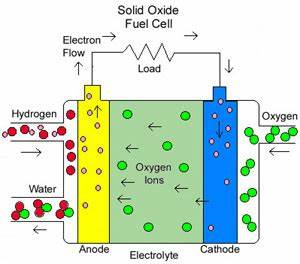
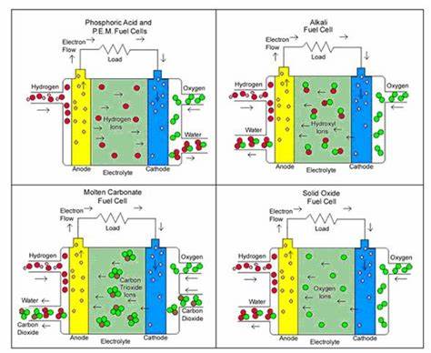
Figure 1: Fuel Cell Diagram Showing Electrochemical Reaction
The exploration and utilization of alternative fuels are essential for creating a sustainable energy future. By diversifying our energy sources and adopting technologies like fuel cells, we can reduce our reliance on fossil fuels and mitigate the environmental impact of energy production. Continued research and development in this field will pave the way for cleaner, more efficient energy solutions.
Unit 5: Layout of Electric Vehicles and Hybrid Vehicles
Introduction
Electric vehicles (EVs) and hybrid vehicles (HEVs) represent a shift in automotive technology towards sustainable transportation. With growing environmental concerns and advancements in battery technology, these vehicles are becoming increasingly popular. This unit explores the layout, advantages, drawbacks, components, and operational principles of electric and hybrid vehicles.
Advantages and Drawbacks of Electric and Hybrid Vehicles
Advantages
- Reduced Emissions: Electric vehicles produce zero tailpipe emissions, while hybrid vehicles lower emissions compared to conventional vehicles.
- Energy Efficiency: Electric motors are more efficient than internal combustion engines, translating to lower energy consumption.
- Lower Operating Costs: EVs and HEVs often have lower fuel and maintenance costs.
- Incentives: Many governments offer tax breaks, rebates, and other incentives to encourage the adoption of electric and hybrid vehicles.
- Quiet Operation: Electric motors operate quietly, reducing noise pollution.
Drawbacks
- Range Anxiety: Limited range on a single charge can deter potential buyers of electric vehicles.
- Charging Infrastructure: Insufficient charging stations may limit the practicality of EVs in some areas.
- Initial Cost: Higher upfront costs compared to traditional vehicles, although this gap is decreasing.
- Battery Degradation: Over time, battery performance can diminish, affecting range and efficiency.
- Environmental Impact: Battery production and disposal have environmental implications, particularly with lithium mining.
System Components
Both electric and hybrid vehicles comprise several critical components that work together to provide efficient operation. The main components include:
- Electric Motor: Converts electrical energy into mechanical energy to drive the vehicle.
- Battery Pack: Stores electrical energy for propulsion. High energy density batteries, such as lithium-ion, are commonly used.
- Controller: Regulates the flow of electricity between the battery and the motor, enabling smooth acceleration and deceleration.
- Regenerative Braking System: Captures energy during braking and converts it back into electrical energy to recharge the battery.
- Onboard Charger: Converts AC power from the grid into DC power to charge the battery.
Electronic Control System
The electronic control system in hybrid vehicles manages the interaction between the internal combustion engine and the electric motor. It optimizes performance and efficiency by determining when to use each power source. Key configurations include:
Different Configurations of Hybrid Vehicles
- Series Hybrid: The electric motor drives the wheels, while the internal combustion engine acts as a generator to charge the battery.
- Parallel Hybrid: Both the internal combustion engine and the electric motor can drive the wheels, providing flexibility in power usage.
- Series-Parallel Hybrid: Combines both series and parallel configurations, allowing for greater efficiency and adaptability based on driving conditions.
Power Split Device
The power split device is crucial in hybrid vehicles, allowing the vehicle to efficiently distribute power between the electric motor and internal combustion engine. This device can vary the power split ratio, optimizing performance and fuel efficiency.
It enables the vehicle to run in all-electric mode, hybrid mode, or engine-only mode, depending on driving conditions and power demand.
High Energy and Power Density Batteries
Battery technology plays a vital role in the performance of electric and hybrid vehicles. Key considerations include:
- Energy Density: Refers to the amount of energy stored per unit volume or mass, influencing the vehicle’s range.
- Power Density: Indicates how quickly energy can be delivered, impacting acceleration and performance.
- Battery Chemistry: Lithium-ion batteries are the most common due to their high energy density and efficiency.
Basics of Fuel Cell Vehicles
Fuel cell vehicles (FCVs) utilize hydrogen gas to produce electricity through an electrochemical reaction, emitting only water vapor as a byproduct. The main components include:
- Fuel Cell Stack: Converts hydrogen and oxygen into electricity.
- Hydrogen Tank: Stores hydrogen gas at high pressure.
- Electric Motor: Drives the vehicle using electricity generated from the fuel cell.
- Controller: Manages the operation of the fuel cell system, ensuring optimal performance.
Fuel cell vehicles offer rapid refueling times and extended ranges compared to battery electric vehicles, making them an attractive alternative in the quest for sustainable transportation.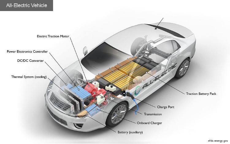
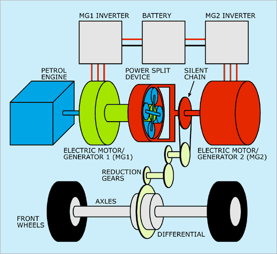
Figure 1: Layout of a Hybrid Vehicle Showing Key Components
The layout of electric and hybrid vehicles represents a significant advancement in automotive technology, combining efficiency with environmental responsibility. As battery technologies improve and charging infrastructure expands, the adoption of these vehicles will likely continue to grow, playing a crucial role in reducing greenhouse gas emissions and promoting sustainable transportation.
Texts References
- V. Ganeshan, “Internal Combustion Engines”, Tata McGraw Hill Publications, New Delhi, 3rd edition.
- J. B. Heywood, “Internal Combustion Engine Fundamentals”, Tata McGraw Hill Publications, New York, International Edition, 1988.
- “Alternative Fuels”, Dr. S. S. Thipse, Jaico publications.
- “IC Engines”, Dr. S. S. Thipse, Jaico publications.
- “Engine Emissions, Pollutant Formation”, G. S. Springer and D.J. Patterson, Plenum Press.
- ARAI Vehicle Emission Test Manual.
- Gerhard Knothe, Jon Van Gerpen, Jargon Krahl, “The Biodiesel Handbook”, AOCS Press, Champaign, Illinois, 2005.
- Richard L. Bechtold P.E., “Alternative Fuels Guidebook”, Society of Automotive Engineers, 1997, ISBN 0-76-80-0052-1.
- Transactions of SAE on Biofuels (Alcohols, Vegetable Oils, CNG, LPG, Hydrogen, Biogas, etc.).
