Engineering Mechanics
Module 1: Basic Concepts
Objectives of Engineering Analysis and Design
The primary objectives of engineering analysis and design include:- Identifying and defining engineering problems.
- Developing models to simulate real-world conditions.
- Optimizing designs for performance, safety, and cost-effectiveness.
- Ensuring compliance with applicable codes and standards.
Idealization of Engineering Problems
Idealization involves simplifying complex real-world problems by making assumptions that help in analyzing them effectively. This is crucial in engineering to create manageable models that can yield practical solutions.Simplification of Real 3D Problems to 2D and 1D Domains
Many engineering problems can be simplified by reducing their dimensionality. This can be done as follows:- 3D to 2D: Assume symmetry to treat a 3D problem in a 2D plane.
- 2D to 1D: For example, beams can be treated as line elements in bending problems.
Basis of Assumptions
Assumptions are made to reduce complexity and focus on essential factors affecting the system. Common assumptions include:- Material properties are homogenous and isotropic.
- Loads are applied gradually and remain constant during analysis.
- Neglecting small deformations or vibrations.
Types of Supports
Supports provide reaction forces and moments to structures. Common types include:- Fixed Support: Restrains all translations and rotations.
- Roller Support: Restrains translations but allows rotation.
- Pinned Support: Restrains translations in all directions but allows rotation.
Types of Loads
Loads can be classified based on their nature and how they are applied:- Static Loads: Loads that do not change over time.
- Dynamic Loads: Loads that vary with time.
- Point Loads: Concentrated forces acting at a single point.
- Distributed Loads: Forces spread over an area.
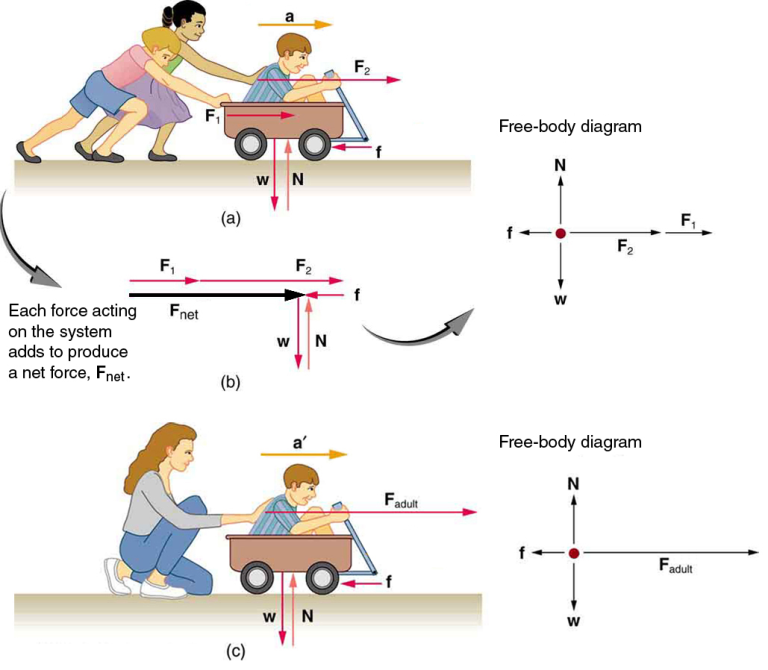
Free Body Diagram
A free body diagram (FBD) is a graphical representation used to visualize the forces acting on a body. It helps in applying Newton’s laws of motion effectively.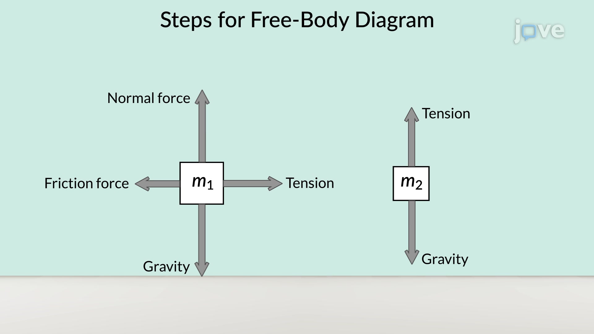

Laws of Motion
The fundamental laws governing the motion of objects are:- Newton’s First Law: An object at rest stays at rest, and an object in motion stays in motion unless acted upon by a net external force.
- Newton’s Second Law: The acceleration of an object is directly proportional to the net force acting on it and inversely proportional to its mass.
Newton’s Second Law
Where:
F = net forcem = mass of the objecta = acceleration
- Newton’s Third Law: For every action, there is an equal and opposite reaction.
Fundamental Principles
Key principles in engineering mechanics include:- Equilibrium: A state where the sum of forces and moments acting on a body is zero.
- Conservation of Energy: Energy cannot be created or destroyed, only transformed from one form to another.
Resolution and Composition of Forces
Forces can be broken down into components (resolution) or combined into a single resultant force (composition).Resolution of Forces
Where:
F_x = horizontal component of the forceF_y = vertical component of the forceF = magnitude of the forceθ = angle of the force from the horizontal
Resultant Forces
The resultant force is the single force that represents the combined effect of all individual forces acting on a body. It can be calculated using vector addition.Resultant Force
Where:
R = resultant forceF_x = sum of all horizontal componentsF_y = sum of all vertical components
Couples and Moments
A couple consists of two equal and opposite forces whose effect is to produce rotation without translation. The moment (Moment of a Couple
Where:
M = momentF = magnitude of one of the forcesd = distance between the forces
Varignon’s Theorem
Varignon’s theorem states that the moment of a force about a point is equal to the sum of the moments of its components about the same point.Varignon’s Theorem
Where:
M_O = moment about point OF = applied forced = perpendicular distance from point O to the line of action of the force
Force Systems
A force system consists of multiple forces acting on a body. They can be classified as:- Concurrent Forces: Forces that meet at a common point.
- Coplanar Forces: Forces that lie in the same plane.
- Collinear Forces: Forces that act along the same line.
Module 2: Equilibrium
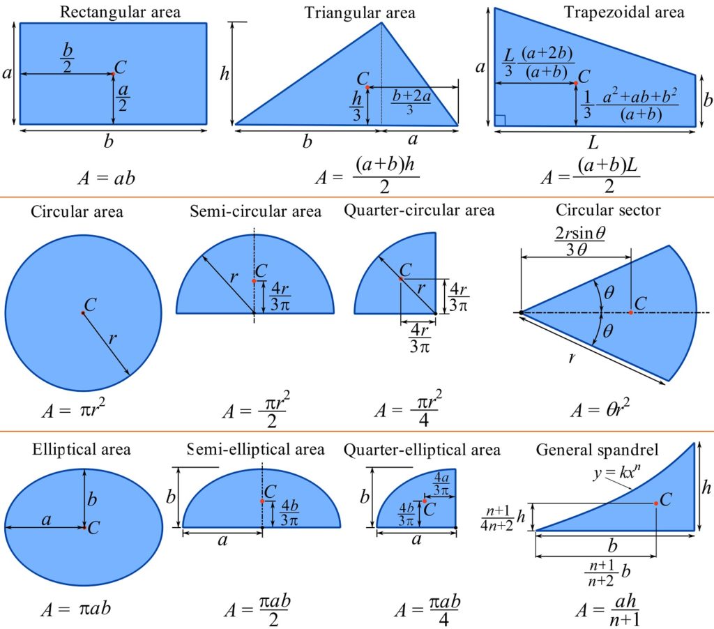
Centroid of Composite Shapes
The centroid is the geometric center of a shape, representing the average position of all points in the shape. For composite shapes, which are made up of two or more basic shapes, the centroid can be calculated using the following formula:
Centroid Calculation
X_c = (Σ(A_i * x_i)) / (ΣA_i)
Y_c = (Σ(A_i * y_i)) / (ΣA_i)
Where:
- X_c, Y_c are the coordinates of the centroid.
- A_i is the area of each component shape.
- x_i, y_i are the coordinates of the centroid of each component shape.
This method involves summing the moments of the individual areas about a chosen axis, divided by the total area to find the centroid’s position.
Moment of Inertia of Plane Sections
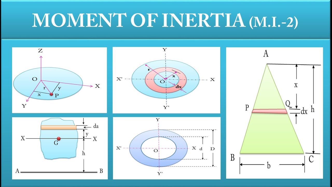
The moment of inertia (I) is a measure of an object’s resistance to rotation about an axis. It plays a crucial role in structural analysis. For a plane section, the moment of inertia is given by:
Moment of Inertia
I = ∫y² dA
Where:
- I is the moment of inertia about a specified axis.
- y is the perpendicular distance from the axis to the area element dA.
This integral sums the contributions of each differential area (dA), multiplied by the square of its distance (y²) from the axis of rotation.
Radius of Gyration
The radius of gyration (k) provides insight into how the mass is distributed about an axis. It is defined as:
Radius of Gyration
k = √(I/A)
Where:
- k is the radius of gyration.
- I is the moment of inertia about the centroidal axis.
- A is the area of the section.
This formula helps in simplifying complex shapes by providing a single distance that represents the distribution of area (or mass) about an axis.
Static Equilibrium
Static equilibrium refers to a state where a body is at rest and the sum of forces and moments acting on it is zero. This can be expressed mathematically as:
Equilibrium Conditions
ΣF = 0 (Sum of all forces is zero)
ΣM = 0 (Sum of all moments is zero)
Where:
- ΣF represents the vector sum of all forces acting on the body.
- ΣM represents the sum of all moments about any point.
These conditions ensure that there is no linear or rotational acceleration in the system.
Analytical and Graphical Conditions of Equilibrium
Equilibrium can be analyzed through two methods:
- Analytical Method: Using algebraic equations based on the equilibrium conditions (ΣF = 0, ΣM = 0).
- Graphical Method: Utilizing graphical techniques like the polygon of forces, where vectors are drawn to scale, ensuring the head-to-tail method leads back to the origin.
Lami’s Theorem
Lami’s theorem applies to three concurrent forces acting on a body in equilibrium. It states that:
Lami’s Theorem
F₁ / sin(α₁) = F₂ / sin(α₂) = F₃ / sin(α₃)
Where:
- F₁, F₂, F₃ are the magnitudes of the forces.
- α₁, α₂, α₃ are the angles opposite to the respective forces.
This theorem is useful for solving problems where three forces act at a point and can simplify the calculations involved.
Equilibrium of Coplanar Concurrent Forces
In coplanar concurrent force systems, all forces act in the same plane and intersect at a single point. The conditions for equilibrium can be expressed using vector addition.
Coplanar Concurrent Forces
ΣF_x = 0, ΣF_y = 0
These conditions indicate that the sum of horizontal and vertical components must equal zero.
Equilibrium of Coplanar Non-Concurrent Forces
In systems with non-concurrent forces, the forces do not meet at a single point, and one must consider moments to achieve equilibrium:
Equilibrium of Non-Concurrent Forces
ΣM = 0
This states that the sum of moments about any point in the plane must also equal zero for equilibrium.
Parallel Forces
Parallel forces are forces that act in the same direction but do not necessarily act at the same point. The resultant of parallel forces can be calculated, and their effect on a body can be determined by considering their moment about a point.
Resultant of Parallel Forces
R = F₁ + F₂ + … + F_n
Where:
- R is the resultant force.
- F₁, F₂, …, F_n are the magnitudes of the individual parallel forces.
The position of the resultant can be found using the principle of moments.
Beams Reactions
In structural analysis, beams must be analyzed to determine the reactions at their supports due to applied loads. The reactions can be calculated using the conditions of equilibrium.
Beam Reactions
ΣF = 0 and ΣM = 0
These equations are applied at the supports to find the reaction forces that maintain the equilibrium of the beam.
Understanding equilibrium is fundamental in engineering design and analysis. Mastery of concepts such as centroids, moments of inertia, and equilibrium conditions allows engineers to ensure stability and functionality in their designs.
Module 3: Friction and Analysis of Trusses
Friction
Friction is a force that opposes the relative motion of two surfaces in contact. It is a crucial factor in engineering as it affects the performance and stability of various mechanical systems. Here are the key concepts related to friction:
Coulomb’s Law of Friction
Coulomb’s Law describes the relationship between the force of friction and the normal force acting on an object:
Coulomb’s Law
F_f = μ * F_n
Where:
- F_f is the force of friction.
- μ is the coefficient of friction (static or kinetic).
- F_n is the normal force acting perpendicular to the surfaces in contact.
This equation indicates that the frictional force is proportional to the normal force and depends on the nature of the surfaces in contact.
Friction Angles
The friction angle (φ) is a measure of the amount of frictional force generated between two surfaces. It is defined in relation to the normal force:
Friction Angle
tan(φ) = μ
Where:
- φ is the angle of friction.
- μ is the coefficient of friction.
This relationship shows how the friction angle relates to the coefficient of friction, providing a geometric interpretation of friction.
Wedge Friction
Wedge friction occurs when a wedge is used to apply a force. The frictional force can be calculated based on the angle of the wedge and the applied load:
Wedge Friction
F_f = P * sin(θ) * μ
Where:
- F_f is the frictional force.
- P is the applied load.
- θ is the angle of the wedge.
- μ is the coefficient of friction.
This formula demonstrates how wedge angles influence frictional forces in mechanical systems.
Sliding Friction
Sliding friction is the resistance encountered when an object slides over another surface. It can be expressed similarly to Coulomb’s law:
Sliding Friction
F_f = μ_k * F_n
Where:
- F_f is the frictional force during sliding.
- μ_k is the coefficient of kinetic friction.
- F_n is the normal force.
This indicates that sliding friction is also dependent on the normal force and the nature of the surfaces in contact.
Rolling Resistance
Rolling resistance is the resistance that occurs when an object rolls over a surface. It is generally much less than sliding friction:
Rolling Resistance
F_r = C_r * F_n
Where:
- F_r is the rolling resistance force.
- C_r is the coefficient of rolling resistance.
- F_n is the normal force.
This formula illustrates that rolling resistance also depends on the normal force, but its coefficient is typically smaller than that of sliding friction.
Analysis of Trusses
Trusses are structural frameworks consisting of interconnected elements that form a rigid structure. They are commonly used in bridges and roofs due to their ability to distribute loads effectively. There are two primary methods for analyzing trusses: the method of joints and the method of sections.
Simple Trusses (Plane and Space)
Trusses can be categorized into plane trusses (2D) and space trusses (3D). A plane truss lies in a single plane, while a space truss exists in three dimensions.
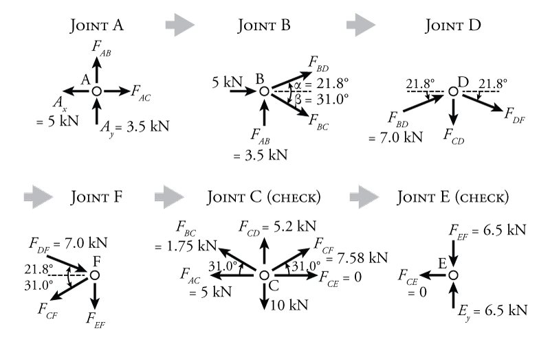
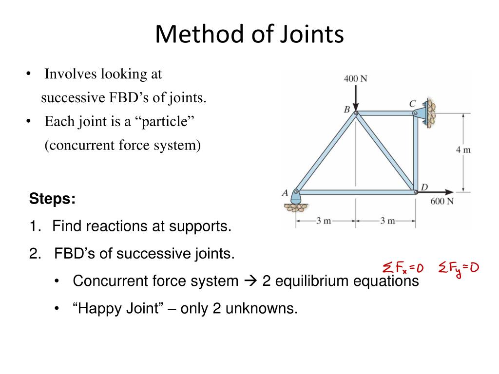
Method of Joints for Plane Trusses
The method of joints involves isolating each joint of the truss to analyze the forces acting on it. The equilibrium conditions for each joint can be expressed as:
Equilibrium Conditions at a Joint
ΣF_x = 0
ΣF_y = 0
Where:
- ΣF_x is the sum of horizontal forces at the joint.
- ΣF_y is the sum of vertical forces at the joint.
This approach ensures that the sum of forces in both horizontal and vertical directions is zero, indicating that the joint is in equilibrium.
 Method of Sections for Plane Trusses
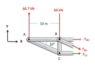
The method of sections involves cutting through the truss to isolate a section and analyzing the forces acting on that section. The equilibrium conditions are similar to those used in the method of joints:
Equilibrium Conditions for a Section
ΣM = 0
Where:
- ΣM is the sum of moments about any point in the section.
This condition allows for the calculation of unknown forces in the truss by summing moments around a point, ensuring rotational equilibrium.
Understanding friction and the analysis of trusses is essential for engineers as they design and evaluate structures. Mastery of these concepts allows for better predictions of performance and safety in engineering applications.
Module 4: Kinematics
Introduction to Kinematics
Kinematics is the branch of mechanics that studies the motion of objects without considering the forces causing the motion. It focuses on describing how objects move and includes concepts such as displacement, velocity, and acceleration.
Types of Motion
Motion can be classified into several types:
- Translational Motion: Movement of an object from one point to another in space.
- Rotational Motion: Movement of an object around an axis.
- Periodic Motion: Motion that repeats itself after a certain period (e.g., pendulum).
- Rectilinear Motion: Motion along a straight line.
- Curvilinear Motion: Motion along a curved path.
Kinematics of Particles
In kinematics, we often analyze the motion of particles. The key parameters involved are displacement, velocity, and acceleration.
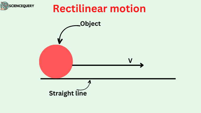
Rectilinear Motion
Rectilinear motion is the simplest form of motion, where an object moves along a straight line. The basic equations of motion for an object under constant acceleration are:
First Equation of Motion
v = u + a * t
Where:
- v = final velocity
- u = initial velocity
- a = acceleration
- t = time
This equation relates the final velocity of an object to its initial velocity, acceleration, and time of travel.
Second Equation of Motion
s = ut + (1/2) * a * t²
Where:
- s = displacement
- u = initial velocity
- a = acceleration
- t = time
This equation provides a relationship between displacement, initial velocity, acceleration, and time.
Third Equation of Motion
v² = u² + 2as
Where:
- v = final velocity
- u = initial velocity
- a = acceleration
- s = displacement
This equation connects the final velocity, initial velocity, acceleration, and displacement, allowing for calculations without needing time.
Constant and Variable Acceleration
Acceleration can be constant or variable. In constant acceleration, the rate of change of velocity is uniform. In variable acceleration, this rate changes over time, often requiring calculus to analyze motion.
Relative Motion
Relative motion refers to the calculation of the motion of an object as observed from another moving object. The relative velocity can be calculated as:
Relative Velocity
v_rel = v_A – v_B
Where:
- v_rel = relative velocity of object A with respect to object B
- v_A = velocity of object A
- v_B = velocity of object B
This formula helps in understanding how the motion of one object affects another object.
Motion Under Gravity
When objects move under the influence of gravity, they experience a uniform acceleration downwards (approximately 9.81 m/s² on Earth). The equations of motion can still apply with the acceleration replaced by gravitational acceleration (g).
Study of Motion Diagrams
Motion diagrams are graphical representations of an object’s position over time. They help visualize the motion, showing the trajectory and any changes in velocity or acceleration.
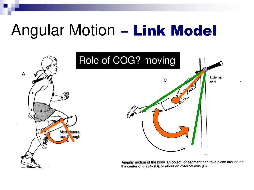
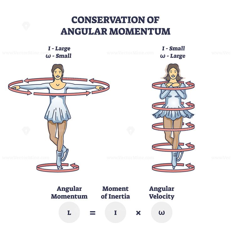
Angular Motion
Angular motion involves the rotation of objects around an axis. The key parameters include angular displacement, angular velocity, and angular acceleration.
Angular Displacement
θ = ω * t
Where:
- θ = angular displacement (radians)
- ω = angular velocity (radians/second)
- t = time (seconds)
This equation relates angular displacement to angular velocity and time.
Angular Acceleration
α = (ω_f – ω_i) / t
Where:
- α = angular acceleration (radians/second²)
- ω_f = final angular velocity
- ω_i = initial angular velocity
- t = time (seconds)
This formula defines angular acceleration as the change in angular velocity over time.
Tangential and Radial Acceleration
In angular motion, two components of acceleration are significant:
- Tangential Acceleration (a_t): The component of acceleration tangent to the circular path.
- Radial Acceleration (a_r): The component directed towards the center of the circular path, also known as centripetal acceleration.
Tangential Acceleration
a_t = r * α
Where:
- a_t = tangential acceleration
- r = radius of the circular path
- α = angular acceleration
This equation shows the relationship between tangential acceleration and angular acceleration.
Radial (Centripetal) Acceleration
a_r = (v²) / r
Where:
- a_r = radial acceleration
- v = linear velocity
- r = radius of the circular path
This formula defines radial acceleration as the linear velocity squared divided by the radius of the path.
Projectile Motion
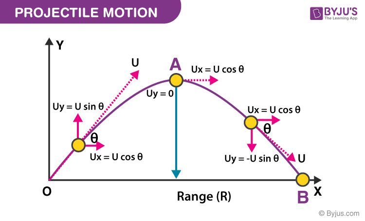
Projectile motion refers to the motion of an object thrown into the air, subject only to the acceleration of gravity. It can be analyzed by separating the motion into horizontal and vertical components.
Projectile Motion Equations
x = u * cos(θ) * t
y = u * sin(θ) * t – (1/2) * g * t²
Where:
- x = horizontal displacement
- y = vertical displacement
- u = initial velocity
- θ = angle of projection
- g = acceleration due to gravity
- t = time
The horizontal motion is uniform, while the vertical motion is uniformly accelerated due to gravity.
Kinematics of Rigid Bodies
Rigid body kinematics deals with the motion of solid bodies without deformation. Key concepts include the instantaneous center of rotation and relative velocity.
Concept of Instantaneous Center of Rotation
The instantaneous center of rotation is the point in a body or system at which all particles have zero velocity at a particular instant. This concept is crucial for analyzing the motion of rigid bodies.
Concept of Relative Velocity
Relative velocity for rigid bodies can be computed using the concept of instantaneous centers. If two rigid bodies are moving, the relative velocity of one body with respect to another can be derived using their velocities and positions relative to the instantaneous center.
Relative Velocity for Rigid Bodies
v_{AB} = v_A – v_B + ω × r_{AB}
Where:
- v_{AB} = relative velocity of A with respect to B
- v_A = velocity of point A
- v_B = velocity of point B
- ω = angular velocity
- r_{AB} = position vector from B to A
This formula combines translational and rotational motion to give the complete picture of relative motion.
Kinematics is a foundational aspect of mechanics that enables us to describe and predict the motion of objects. Understanding the various types of motion, the equations governing them, and the key concepts in kinematics is essential for further studies in physics and engineering.
Module 5: Kinetics and Work, Power, Energy
Introduction to Kinetics
Kinetics is the branch of mechanics that deals with the forces acting on objects and the resulting motion. It extends the principles of kinematics by considering the effects of forces and torques on the motion of particles and rigid bodies.
Mass Moment of Inertia
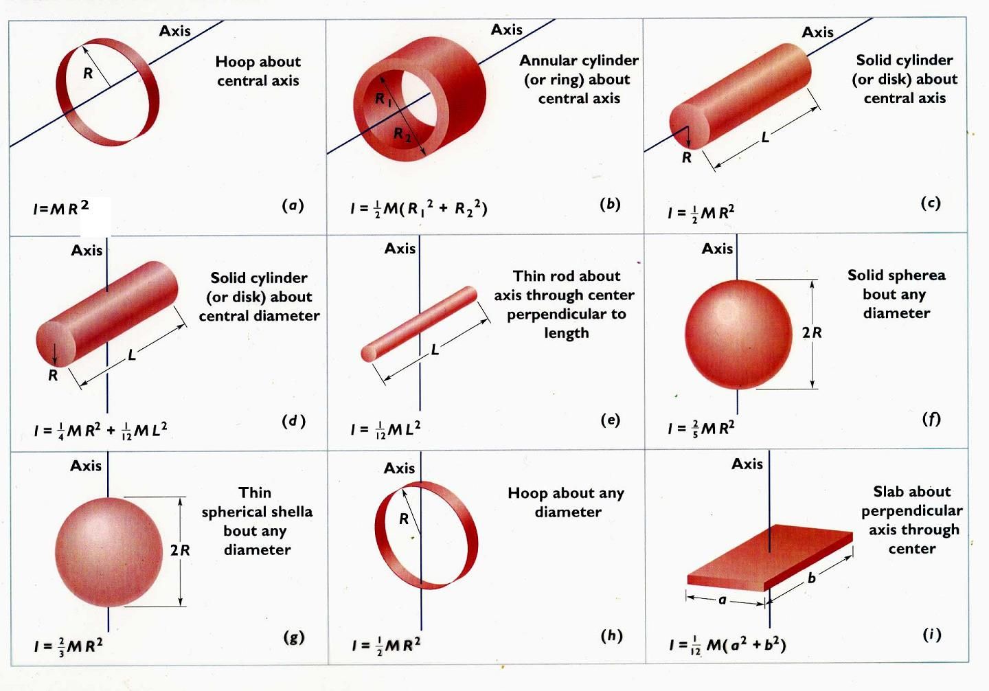
The mass moment of inertia (I) is a measure of an object’s resistance to angular acceleration about an axis. It depends on the mass distribution relative to the axis of rotation.
Mass Moment of Inertia
I = Σ m_i * r_i²
Where:
- I = mass moment of inertia
- m_i = mass of each particle
- r_i = distance from the axis of rotation
This formula sums the products of the mass of each particle and the square of its distance from the axis of rotation, highlighting how distribution affects inertia.
Kinetics of Particles
The kinetics of particles focuses on analyzing the motion of particles using Newton’s laws of motion.
Newton’s Second Law
F = m * a
Where:
- F = net force acting on the particle
- m = mass of the particle
- a = acceleration of the particle
This fundamental law states that the acceleration of a particle is directly proportional to the net force acting on it and inversely proportional to its mass.
D’Alembert’s Principle
D’Alembert’s principle provides a method to analyze dynamics by considering inertial forces. It states that the sum of the differences between the forces acting on a system and the inertial forces is zero.
D’Alembert’s Principle
Σ (F – ma) = 0
Where:
- ΣF = sum of external forces
- m = mass of the particle
- a = acceleration
This principle allows us to treat dynamics problems as static equilibrium problems by introducing inertial forces.
Applications in Linear Motion
In linear motion, D’Alembert’s principle can be applied to derive equations of motion for a particle acted upon by external forces.
Kinetics of Rigid Bodies
Kinetics of rigid bodies examines the effects of forces and torques on the motion of solid objects. The analysis can be broken down into two main applications: translation and fixed axis rotation.
Applications in Translation
For rigid bodies in translational motion, the same principles of particle kinetics apply, with the addition of considering rotational effects.
Applications in Fixed Axis Rotation
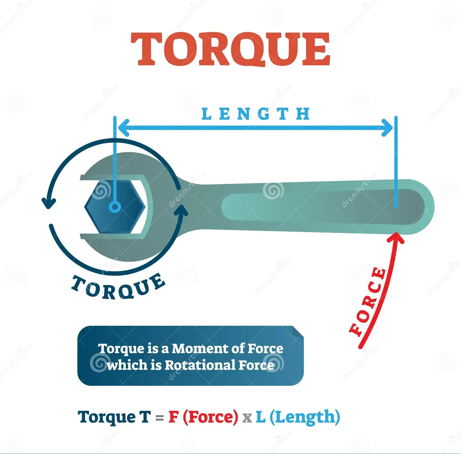
For rotation about a fixed axis, the net torque about the axis must be considered.
Torque
τ = I * α
Where:
- τ = torque
- I = mass moment of inertia
- α = angular acceleration
This equation shows the relationship between torque, moment of inertia, and angular acceleration.
Principle of Virtual Work
The principle of virtual work states that the work done by external forces during virtual displacements is zero for a system in equilibrium.
Virtual Displacements for Particle and Rigid Bodies
Virtual displacement refers to an imagined infinitesimal change in the position of a system, which does not actually occur.
Work Done by a Force
Work done (W) by a force (F) during displacement (s) can be expressed as:
Work Done
W = F * s * cos(θ)
Where:
- W = work done
- F = magnitude of the force
- s = displacement
- θ = angle between the force and displacement vector
This formula calculates the work done based on the force applied, the displacement achieved, and the angle between them.
Potential and Kinetic Energy
Energy is the capacity to do work. In mechanical systems, we consider two types of energy:
Potential Energy (PE)
Potential energy is the stored energy in an object due to its position or configuration.
Gravitational Potential Energy
PE = m * g * h
Where:
- PE = potential energy
- m = mass of the object
- g = acceleration due to gravity
- h = height above a reference point
This formula represents the gravitational potential energy of an object at height h.
Kinetic Energy (KE)
Kinetic energy is the energy of motion. For linear motion, it is given by:
Kinetic Energy
KE = (1/2) * m * v²
Where:
- KE = kinetic energy
- m = mass of the object
- v = velocity of the object
This equation indicates that kinetic energy increases with the square of the velocity.
Kinetic Energy of Rotation
For rotating bodies, the kinetic energy can be expressed as:
Kinetic Energy of Rotation
KE_rot = (1/2) * I * ω²
Where:
- KE_rot = rotational kinetic energy
- I = mass moment of inertia
- ω = angular velocity
This formula describes the kinetic energy of a rigid body in rotation.
Work-Energy Equation
The work-energy principle states that the work done by the net force on an object is equal to the change in its kinetic energy.
Work-Energy Principle
W_net = ΔKE
Where:
- W_net = work done by net force
- ΔKE = change in kinetic energy
This relationship illustrates how work affects the energy state of a system.
Conservation of Energy
The principle of conservation of energy states that the total energy of an isolated system remains constant. Energy can neither be created nor destroyed; it can only be transformed from one form to another.
Power
Power (P) is the rate at which work is done or energy is transferred over time.
Power
P = W / t
Where:
- P = power
- W = work done
- t = time taken
This formula indicates that power is directly related to both work done and the time taken to do that work.
Impulse-Momentum Principle
The impulse-momentum principle states that the impulse (force multiplied by the time interval) acting on an object results in a change in momentum.
Impulse-Momentum
J = Δp
Where:
- J = impulse
- Δp = change in momentum
This principle links force applied over a time period to changes in the object’s momentum.
Collision of Elastic Bodies
In elastic collisions, both momentum and kinetic energy are conserved. The equations governing elastic collisions can be used to determine the final velocities of colliding bodies.
Conservation of Momentum in Elastic Collisions
m₁ * v₁ + m₂ * v₂ = m₁ * v₁’ + m₂ * v₂’
Where:
- m₁, m₂ = masses of the colliding bodies
- v₁, v₂ = initial velocities
- v₁’, v₂’ = final velocities after collision
This equation ensures that the total momentum before and after the collision remains the same.
Understanding the principles of kinetics and energy is crucial for analyzing mechanical systems. These concepts form the foundation for studying dynamics and the behavior of physical systems under various forces and motions.
Text Books:
1. S. Timoshenko, D. H. Young, “Engineering Mechanics”, McGraw Hill, 1995.
2. Tayal A. K., “Engineering Mechanics”, Umesh Publications, 2010.
3. Bhavikatti S. S., Rajashekarappa K. G., “Engineering Mechanics”, New Age International Publications,
2nd Edition.
4. Beer, Johnston, “Vector Mechanics for Engineers”, Vol. 1: Statics and Vol. 2: Dynamics, McGraw Hill
Company Publication, 7th edition, 1995.
5. Khurmi R. S., “Engineering Mechanics”, S. Chand Publications,N. Delhi.
Reference Books:
1. Irving H. Shames, “Engineering Mechanics -Statics and Dynamics”, Pearson Educations, Fourth edition,
2003.
2. McLean, Nelson, “Engineering Mechanics”, Schaum‟s outline series, McGraw Hill Book Company, N.
Delhi, Publication.
3. Singer F. L., “Engineering Mechanics -Statics & Dynamics”, Harper and Row Pub. York.
4. Junnarkar S.B., and Shah, H.J. “Applied Mechanics”, Charotar Publication House Anand
