Engineering Physics
Unit I: Oscillation and Ultrasonics
1. Free Oscillation
Free oscillation, also called natural oscillation, occurs when a system oscillates without the influence of any external force after being displaced from its equilibrium position. It continues to move due to the restoring force that tries to bring it back to equilibrium. A perfect example of this is a simple pendulum or a mass-spring system.
The most important characteristic of free oscillation is that it happens at the natural frequency of the system. This frequency depends on the physical properties of the system, such as mass and stiffness. In the absence of damping, the oscillation continues with constant amplitude indefinitely.
The restoring force in free oscillation is proportional to the displacement from the equilibrium position, which follows Hooke’s Law. Mathematically, it can be expressed as:
Where:
F = Restoring force that brings the system back to equilibrium
k = Spring constant (or stiffness constant), which measures the stiffness of the system
x = Displacement from the equilibrium position
The negative sign indicates that the force is directed opposite to the displacement.
Free oscillations are described by a second-order differential equation:
Where:
m = Mass of the oscillating body
x = Displacement from equilibrium
t = Time
This equation models a system undergoing harmonic motion, where the solution is a sinusoidal function of time.
The general solution for this equation is:
Where:
A = Amplitude of the oscillation (maximum displacement)
ω = Angular frequency of the oscillation
t = Time
φ = Phase constant, which depends on the initial conditions of the system.
The angular frequency, ω, is related to the mass and the spring constant as:
This shows that the frequency of oscillation depends on the properties of the system, particularly its stiffness (k) and mass (m). The larger the stiffness, the faster the oscillation; the larger the mass, the slower the oscillation.
2. Damped Oscillation
Damped oscillation refers to the scenario where energy is gradually lost to the surroundings due to resistive forces like friction or air resistance. As a result, the amplitude of the oscillation decreases over time, and eventually, the system comes to rest.
The damping force in this case is proportional to the velocity of the oscillating body and acts in the opposite direction, reducing the speed of motion. Mathematically, this can be modeled as:
Where:
b = Damping coefficient (which represents the strength of the damping force)
m = Mass of the system
x = Displacement from the equilibrium position
k = Spring constant
dx/dt = Velocity
The term “b * dx/dt” represents the damping force.
Damped oscillations can be classified into three types based on the value of the damping coefficient (b):
- Light Damping: The system oscillates with gradually decreasing amplitude, but it continues to oscillate for a relatively long period before coming to rest.
- Critical Damping: The system returns to equilibrium as quickly as possible without oscillating. This is the most efficient form of damping.
- Heavy Damping: The system returns to equilibrium very slowly without oscillating.
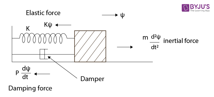
Figure: Representation of Damped Oscillation
The solution to the damped oscillation equation is a decaying sinusoidal function:
Where:
A = Initial amplitude
b = Damping coefficient
ω’ = Damped angular frequency
t = Time
φ = Phase constant
The term “e^(-bt/2m)” represents the exponential decay of the amplitude over time.
3. Forced Oscillation and Resonance
In forced oscillation, an external periodic force is applied to the system, which keeps it oscillating indefinitely. Unlike free or damped oscillation, the amplitude here depends on the frequency of the external force.
The equation of motion for forced oscillation is:
Where:
F₀ = Amplitude of the applied external force
ω = Angular frequency of the external force
The system is subject to a continuous driving force “F₀ * cos(ωt)” which keeps the oscillation going.
One of the most significant phenomena that occur in forced oscillation is resonance. This occurs when the frequency of the external force matches the natural frequency of the system. At resonance, the system oscillates with maximum amplitude, and in the case of light damping, this can lead to very large oscillations.
The frequency at which resonance occurs is the natural frequency of the system:
Resonance is utilized in many practical applications such as tuning musical instruments, designing bridges to avoid collapse under specific frequencies, and in radio and television receivers to pick up desired signals.
4. Differential Wave Equation
Waves, such as sound waves or water waves, propagate through a medium by transferring energy from one point to another. The differential wave equation is a second-order partial differential equation that describes the behavior of wave propagation.
The wave equation in its simplest form is:
Where:
y = Displacement of the wave
x = Position along the wave’s path
t = Time
v = Wave velocity
This equation describes how the displacement y of a wave changes with both time and space.
5. Ultrasonics
Ultrasonics refers to sound waves that have a frequency higher than the audible range of human hearing, which is approximately 20 kHz. Ultrasonic waves have a wide range of applications in various fields, such as medical imaging, industrial non-destructive testing, cleaning, and even in animals like bats for echolocation.
The generation of ultrasonic waves can be achieved by various methods, including:
- Piezoelectric Effect: In this method, certain materials (such as quartz) generate ultrasonic waves when subjected to mechanical stress. The reverse piezoelectric effect is often used to generate ultrasound waves for industrial and medical applications.
- Magnetostriction: This method uses ferromagnetic materials, which change in length when subjected to a magnetic field, generating ultrasonic waves. Though less efficient than the piezoelectric method, it is still used in some applications.
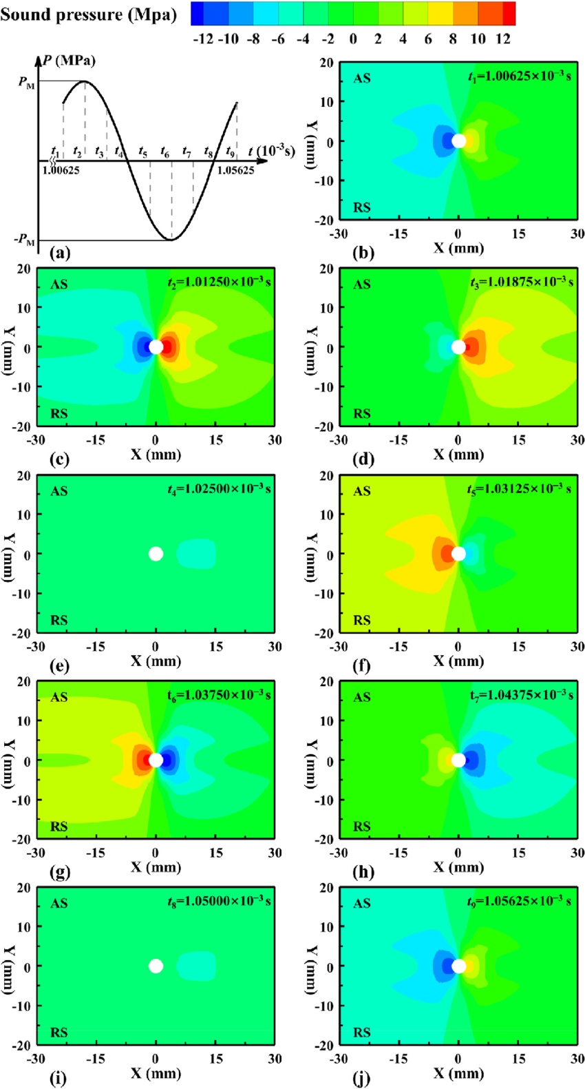
Some important applications of ultrasonics include:
- Medical Imaging: Ultrasonics is extensively used in medical diagnostics, particularly in ultrasonography. High-frequency sound waves are transmitted into the body, and the reflected waves are used to form images of internal structures.
- Industrial Testing: Ultrasonic waves are used to detect cracks and imperfections in materials, especially metals, in non-destructive testing (NDT).
- Cleaning: Ultrasonic cleaners use high-frequency sound waves to clean delicate objects like jewelry, lenses, and electronic components.
- Echolocation: Bats and dolphins use ultrasonics to navigate and locate objects in their surroundings by emitting high-frequency sound waves and analyzing the returning echoes.
6. Production of Ultrasonics
6.1 Piezoelectric Effect
The piezoelectric effect is the ability of certain materials to generate an electric charge in response to applied mechanical stress. It is used to produce ultrasonic waves by applying alternating current to a piezoelectric crystal, causing it to vibrate at high frequencies.
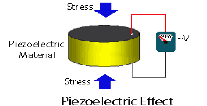
Figure: Production of Ultrasonics Using the Piezoelectric Effect
6.2 Magnetostriction Effect
The magnetostriction effect refers to the change in the shape of ferromagnetic materials when subjected to a magnetic field. This change in shape is used to produce ultrasonic waves by converting magnetic energy into mechanical vibrations.
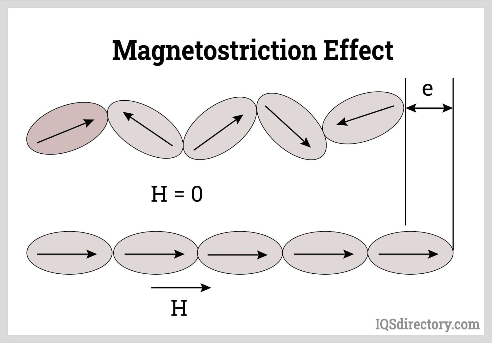
Figure: Production of Ultrasonics Using the Magnetostriction Effect
7. Applications of Ultrasonics
Ultrasonic waves have a wide range of applications:
- Medical Imaging (Ultrasound): Ultrasonics are used for imaging internal body structures, such as in fetal imaging.
- Industrial Testing: Ultrasonics are used for non-destructive testing to detect flaws in materials and structures.
- Cleaning: Ultrasonic cleaning uses high-frequency sound waves to clean delicate objects and instruments.
- Sonar: Ultrasonics are used in sonar systems to detect objects underwater by sending out sound waves and analyzing the echoes.
Unit II: Optics, Fibre Optics, and Laser
1. Interference of Light in Thin Films
Interference is a fundamental phenomenon in optics that occurs when two or more coherent light waves superimpose to produce a resultant wave. This can result in regions of constructive interference, where the light intensities add together, and destructive interference, where they cancel each other out. The most common manifestation of interference is observed in thin films, such as soap bubbles or oil slicks on water, where the varying thickness of the film leads to a beautiful spectrum of colors.
When light strikes a thin film, part of it reflects off the top surface, while part of it penetrates the film and reflects off the bottom surface. The two reflected waves can interfere with each other. The phase difference between these two waves depends on the optical path length difference, which is influenced by the thickness of the film and the wavelength of light.
The path difference (\(Δ\)) between the two waves can be expressed by the formula:
Where:
- Δ = Path difference
- μ = Refractive index of the medium
- t = Thickness of the thin film
- r = Angle of refraction inside the thin film
For constructive interference (bright fringes), the condition is that the path difference should be an integer multiple of the wavelength:
Conversely, for destructive interference (dark fringes), the condition is:
Here, \(m\) is an integer (0, 1, 2, …). The colorful patterns seen in thin films result from the varying thicknesses of the film, leading to different conditions for constructive and destructive interference at different points.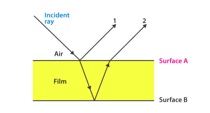
2. Wedge-Shaped Film
A wedge-shaped film is a thin film where the thickness varies linearly from one end to the other. This setup is used to create interference patterns due to the changing thickness, leading to a series of light and dark fringes. The wedge-shaped film can be formed by placing two glass plates at a slight angle to each other.
In this scenario, the path difference for light reflecting off the two surfaces of the wedge can be expressed by:
Where:
- t = Thickness of the wedge at a particular point
- μ = Refractive index of the material
- λ = Wavelength of light
- m = Order of interference fringe
As the thickness of the film changes, the path difference between the two reflected waves changes, leading to an alternating pattern of constructive and destructive interference. This produces a series of bright and dark fringes, which can be observed and analyzed to determine the properties of the light and the material of the film.
The spacing between the fringes is directly related to the angle of the wedge and the wavelength of the light. The mathematical relationship can be derived based on the geometry of the wedge and the interference conditions, making this setup an important tool in optical experiments.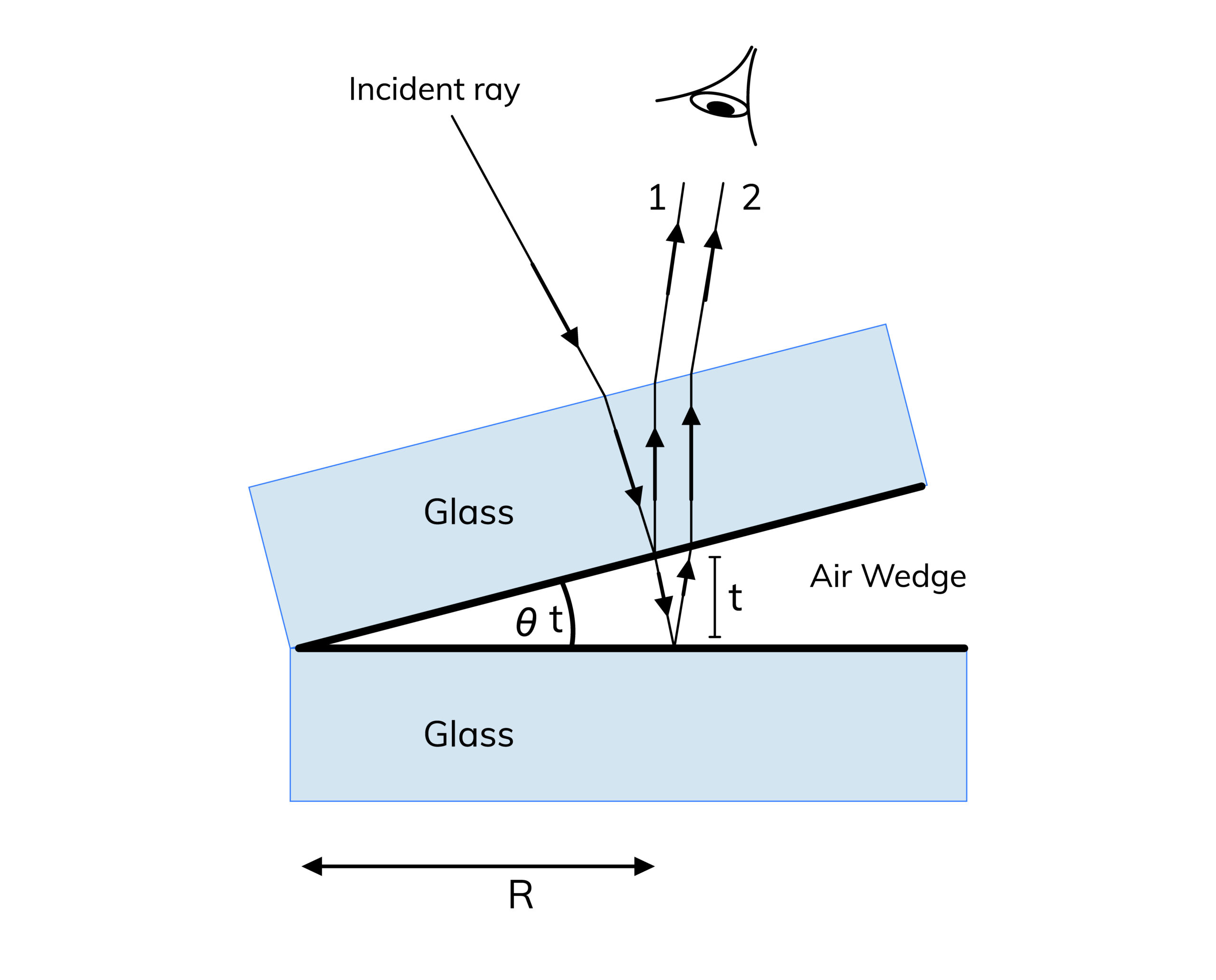
3. Newton’s Rings
Newton’s rings are a fascinating demonstration of the interference of light, produced by the reflection of light between a spherical surface and a flat surface. When a plano-convex lens is placed on a flat glass surface, air forms a thin film of varying thickness between the two. When monochromatic light is directed onto this arrangement, it results in a pattern of concentric circles of alternating bright and dark fringes, known as Newton’s rings.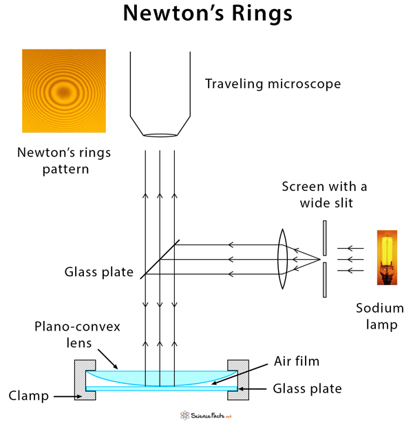
The radius of the n-th bright ring can be calculated using the formula:
Where:
- r_n = Radius of the nth bright ring
- λ = Wavelength of light used
- R = Radius of curvature of the lens
- n = Order of the ring (n = 0, 1, 2, …)
- μ = Refractive index of the medium (usually air, μ ≈ 1)
The rings appear because light reflecting off the top and bottom surfaces of the air film undergoes interference. The constructive interference occurs at specific points where the path difference is an integer multiple of the wavelength, resulting in bright fringes. Dark fringes correspond to points of destructive interference.
The study of Newton’s rings is not only a beautiful illustration of interference but also serves practical purposes, such as determining the wavelength of light or measuring the radius of curvature of lenses.
4. Polarization of Light
Polarization of light is the process by which light waves are made to oscillate in a particular direction. Most light sources emit unpolarized light, which consists of waves oscillating in all directions perpendicular to the direction of propagation. Polarization can reduce glare and improve contrast, which is why polarized sunglasses are popular.
Light can be polarized through several methods, each of which exploits different physical phenomena:
- Reflection: When light reflects off a non-metallic surface at a specific angle known as Brewster’s angle, the reflected light becomes partially or fully polarized. This is because the reflected waves corresponding to the electric field vibrating parallel to the surface are reflected more strongly than those vibrating perpendicular.
- Refraction: When light passes through certain materials, such as polarizing filters or crystals, the refracted light can become partially polarized due to differences in the refractive indices for different polarization states.
- Double Refraction: Some crystals, like calcite or quartz, exhibit birefringence, meaning they have different refractive indices depending on the polarization direction. When unpolarized light enters such a crystal, it splits into two rays, each with different polarizations and speeds.
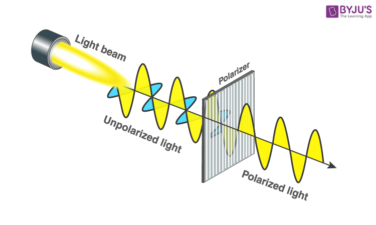
Polarized light has many applications, including in photography, liquid crystal displays (LCDs), and optical instruments. Understanding how to manipulate light polarization is crucial in designing optical systems that improve visibility and reduce glare.
Huygens’ Theory of Double Refraction
Huygens’ principle states that every point on a wavefront can be considered as a source of secondary wavelets. In the context of double refraction, when an incoming light wave hits a birefringent crystal, the wavefront is split into two distinct wavefronts that travel at different speeds due to the crystal’s unique properties.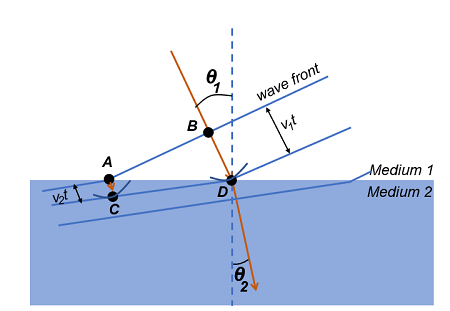
These two emerging rays are termed the ordinary ray and the extraordinary ray. The ordinary ray behaves according to Snell’s law and has a consistent velocity regardless of the angle of incidence. In contrast, the extraordinary ray’s speed depends on the angle of incidence relative to the crystal’s optical axis.
The phenomenon of double refraction leads to fascinating optical effects and is foundational for the study of optical crystals and their applications in optics and photonics.
5. Principle and Structure of Optical Fibre
Optical fibers are flexible, transparent fibers made of glass or plastic that transmit light between their ends. The principle behind optical fibers is total internal reflection, which occurs when light traveling through a medium hits the boundary with a less dense medium at an angle greater than the critical angle.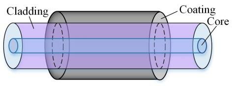
The structure of an optical fiber typically consists of three layers:
- Core: The central part of the fiber, made of a material with a high refractive index, where the light is transmitted.
- Cladding: The outer layer surrounding the core, made of a material with a lower refractive index. This layer reflects the light back into the core, facilitating total internal reflection.
- Jacket: The protective outer layer that shields the fiber from physical damage and environmental factors.
The acceptance angle (\(θ_a\)) is defined as the maximum angle at which light can enter the fiber and still be guided through it, leading to effective total internal reflection. The relationship between the acceptance angle, refractive indices, and critical angle can be expressed as:
Where:
- θ_a = Acceptance angle
- n_1 = Refractive index of the core
- n_2 = Refractive index of the cladding
The numerical aperture (NA) of an optical fiber quantifies its ability to collect light and can be calculated as follows:
A higher numerical aperture indicates a greater capacity for collecting light, which is essential for applications like telecommunications and medical instruments. Optical fibers have revolutionized communication technology by allowing for high-speed data transmission over long distances with minimal loss.
6. Principle of Laser
The term “laser” stands for Light Amplification by Stimulated Emission of Radiation. The principle of laser operation is based on three essential processes: population inversion, stimulated emission, and optical feedback.
In a laser medium, atoms or molecules are excited to higher energy levels through external energy input (pumping). When a sufficient number of particles achieve a higher energy state, population inversion occurs. This is crucial because, under normal circumstances, there are more particles in lower energy states than in higher ones.
When an excited atom returns to a lower energy state, it can release its stored energy in the form of a photon. If this photon encounters another excited atom, it can stimulate that atom to emit another photon of the same energy, phase, and direction, leading to a chain reaction of photon emissions—this is known as stimulated emission.
The laser cavity, formed by mirrors at each end, allows the photons to bounce back and forth, stimulating more emissions and amplifying the light. The output is a highly coherent and monochromatic beam of light, which is highly directional and possesses a specific wavelength.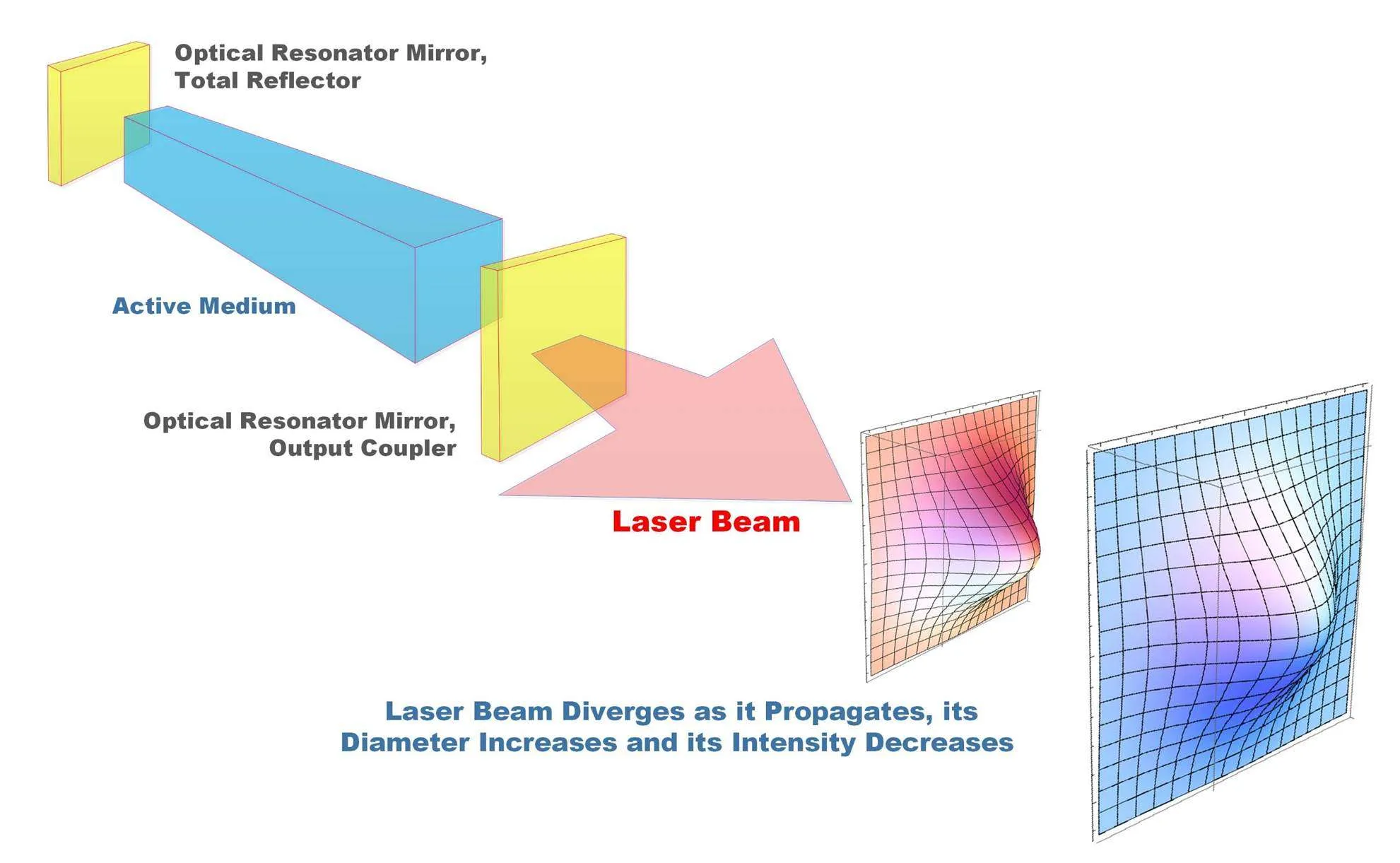
Types of Laser
Two common types of lasers are the Ruby laser and the Helium-Neon (He-Ne) laser, each with unique characteristics and applications.
1. Ruby Laser
The Ruby laser is a solid-state laser that uses a synthetic ruby crystal as its gain medium. The ruby crystal contains chromium ions, which provide the necessary energy levels for laser action. When pumped with a flash lamp, the chromium ions are excited, leading to population inversion. The laser emits light at a wavelength of approximately 694.3 nm in the visible spectrum.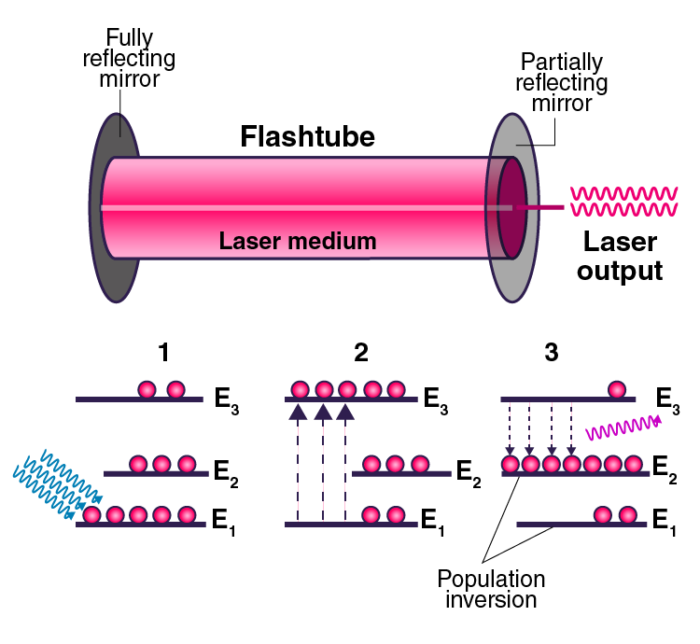
The Ruby laser is known for producing high-energy pulses and is used in various applications, including:
- Medical procedures, such as tattoo removal and hair removal.
- Industrial cutting and welding processes.
- In research, for spectroscopic analysis.
2. Helium-Neon Laser
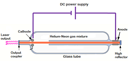
The Helium-Neon (He-Ne) laser is a gas laser that emits red light at a wavelength of 632.8 nm. It consists of a mixture of helium and neon gases contained in a sealed tube. An electric current is passed through the gas mixture, exciting the helium atoms. Energy is then transferred from helium to neon, leading to stimulated emission and the production of coherent light.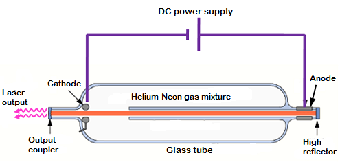
The He-Ne laser is widely used in applications such as:
- Laser pointers and alignment tools.
- Optical communications and fibre optic technology.
- Interferometry and holography in scientific research.
Applications of Lasers
Lasers have become integral in various fields due to their unique properties. Some notable applications include:
- Medical Applications: Lasers are used in precision surgeries, including laser eye surgery (LASIK) and the removal of tumors.
- Industrial Applications: Laser cutting and welding are widely used in manufacturing processes for their precision and efficiency.
- Communication: Lasers are critical in fibre optic communication, enabling high-speed data transmission.
- Scientific Research: Lasers play a crucial role in spectroscopy, holography, and other experimental setups.
The versatility and efficiency of lasers make them invaluable tools across various domains, impacting technology, healthcare, and science profoundly.
Unit III: Electron Optics, Nuclear and Quantum Mechanics
1. Motion of Electron in Electric Field
The motion of an electron in an electric field can be analyzed for both parallel and perpendicular orientations to the field. When an electron is placed in an electric field (\(E\)), it experiences a force given by:
Where:
- F = Force acting on the electron
- e = Charge of the electron (\(1.6 \times 10^{-19} C\))
- E = Electric field strength (in N/C)
In the case of parallel motion, the acceleration (\(a\)) of the electron can be expressed as:
Where \(m\) is the mass of the electron (\(9.11 \times 10^{-31} kg\)). The displacement (\(s\)) of the electron after time \(t\) is given by:
Where \(u\) is the initial velocity of the electron. This formula allows us to calculate the distance traveled by the electron in the electric field.
Perpendicular Motion
When an electron moves perpendicular to the electric field, it will experience a force causing it to accelerate in the direction of the field. The trajectory will resemble a parabolic path, as the electric field exerts a constant force, changing the electron’s velocity over time.
2. Motion of Electron in Magnetic Field
When an electron enters a magnetic field (\(B\)), it experiences a magnetic force given by the Lorentz force equation:
Where:
- F = Magnetic force
- v = Velocity of the electron
- B = Magnetic field strength
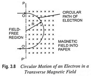
The motion of the electron in a magnetic field is circular, with the radius (\(r\)) of the circular path given by:
This formula demonstrates that the radius of the electron’s path is directly proportional to its velocity and inversely proportional to the magnetic field strength. The frequency (\(f\)) of the circular motion, known as the cyclotron frequency, can be calculated as:
The motion can be visualized as a spiral path when the electron also has a velocity component parallel to the magnetic field.
3. Motion of Electron in Combined Electric and Magnetic Fields
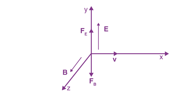
In a situation where both electric and magnetic fields are present, the total force acting on the electron is the vector sum of the forces due to each field:
The electron’s motion can be complex, as it may spiral or move in a more intricate path depending on the relative magnitudes and directions of the fields. For specific configurations, the motion can be periodic, leading to applications in devices such as cathode ray tubes.
4. Bainbridge Mass Spectrograph
The Bainbridge mass spectrograph is a device used to determine the masses of ions. It employs both electric and magnetic fields to separate ions based on their mass-to-charge ratio (\(m/z\)).
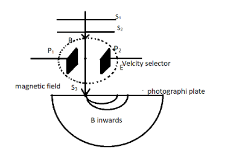
The principle of operation involves the following steps:
- Ions are accelerated through an electric field, gaining kinetic energy proportional to their charge.
- As they enter a magnetic field, the Lorentz force acts on the ions, causing them to follow circular paths.
- The radius of the path is determined by the mass-to-charge ratio, allowing for separation and identification of the ions.
The radius of the path can be expressed as:
Here, \(m\) is the mass of the ion, \(v\) is its velocity, \(e\) is the charge, and \(B\) is the magnetic field strength. By analyzing the radii of different ions, the spectrograph can determine their masses with high precision.
5. Geiger-Müller Counter
The Geiger-Müller (G.M.) counter is an instrument used for detecting and measuring ionizing radiation. It consists of a Geiger-Müller tube filled with gas and a counting mechanism.
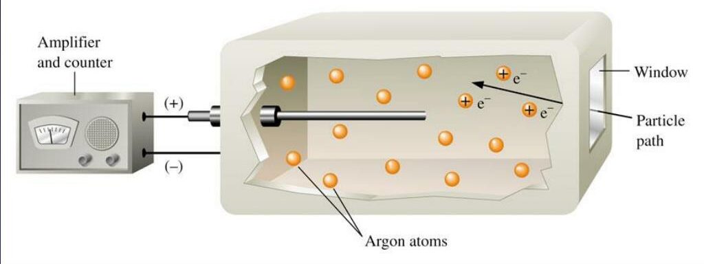
The operation involves the following steps:
- When ionizing radiation enters the tube, it ionizes the gas, creating electron-ion pairs.
- A voltage applied across the tube causes these free electrons to accelerate towards the anode, producing an avalanche effect.
- This avalanche generates a detectable pulse of current, which is counted by the electronic circuitry.
The G.M. counter is widely used in radiation protection, nuclear industry, and research applications to monitor radiation levels and ensure safety.
6. Heisenberg’s Uncertainty Principle
The Heisenberg Uncertainty Principle is a fundamental concept in quantum mechanics stating that certain pairs of physical properties, such as position (\(x\)) and momentum (\(p\)), cannot both be precisely known at the same time. Mathematically, it is expressed as:
Where:
- Δx = Uncertainty in position
- Δp = Uncertainty in momentum
- ħ = Reduced Planck’s constant (\(1.055 \times 10^{-34} Js\))
This principle emphasizes the intrinsic limitations of measurement at the quantum level, leading to profound implications for the nature of reality and the behavior of subatomic particles. It indicates that the more accurately one property is known, the less accurately the other can be determined.
7. Schrödinger’s Wave Equations
The behavior of quantum particles is described by wave functions, which are solutions to Schrödinger’s wave equations. There are two forms: the time-dependent and the time-independent wave equations.
Time-Dependent Schrödinger Equation
The time-dependent wave equation is given by:
Where:
- ψ(x,t) = Wave function
- V(x) = Potential energy as a function of position
- i = Imaginary unit
- ħ = Reduced Planck’s constant
This equation describes how the wave function evolves over time, capturing the dynamic behavior of quantum systems.
Time-Independent Schrödinger Equation
The time-independent wave equation is used for systems where the potential energy does not change with time:
Where:
- E = Total energy of the system
This equation allows us to find the stationary states of a quantum system, providing critical insights into the energy levels and allowed states of particles in various potentials.
8. Physical Significance of the Wave Function
The wave function (\(ψ\)) is a fundamental concept in quantum mechanics, representing the state of a quantum system. Its square modulus, \(|ψ|^2\), gives the probability density of finding a particle in a specific location:
Where \(P(x)\) is the probability density. This interpretation implies that quantum mechanics fundamentally differs from classical physics, as particles do not have definite positions until measured.
The wave function also contains information about the system’s energy, momentum, and other physical properties, making it a central element in understanding quantum mechanics.
Unit IV: Crystal Structure, X-rays, and Electrodynamics
1. Unit Cell
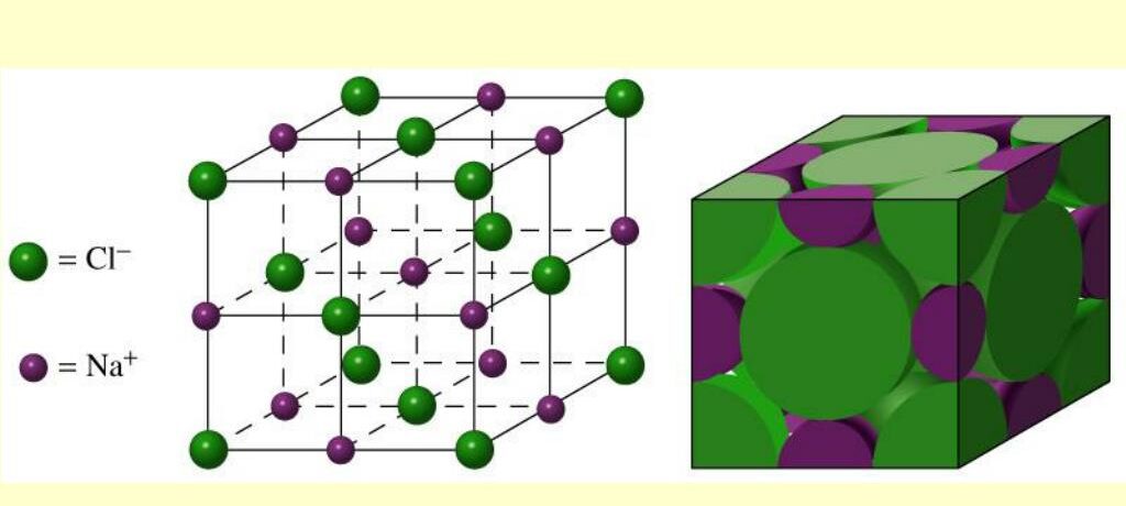
A unit cell is the smallest repeating unit in a crystal lattice. It represents the symmetry and arrangement of atoms in a crystal structure. The unit cell is defined by its parameters: edge lengths (\(a\), \(b\), and \(c\)) and the angles (\(\alpha\), \(\beta\), and \(\gamma\)) between these edges. The most common types of unit cells include:
- Cubic: All edges are equal, and all angles are \(90^\circ\).
- Tetragonal: Two edges are equal, and angles are \(90^\circ\).
- Orthorhombic: All edges are different, and angles are \(90^\circ\).
2. Bravais Lattice
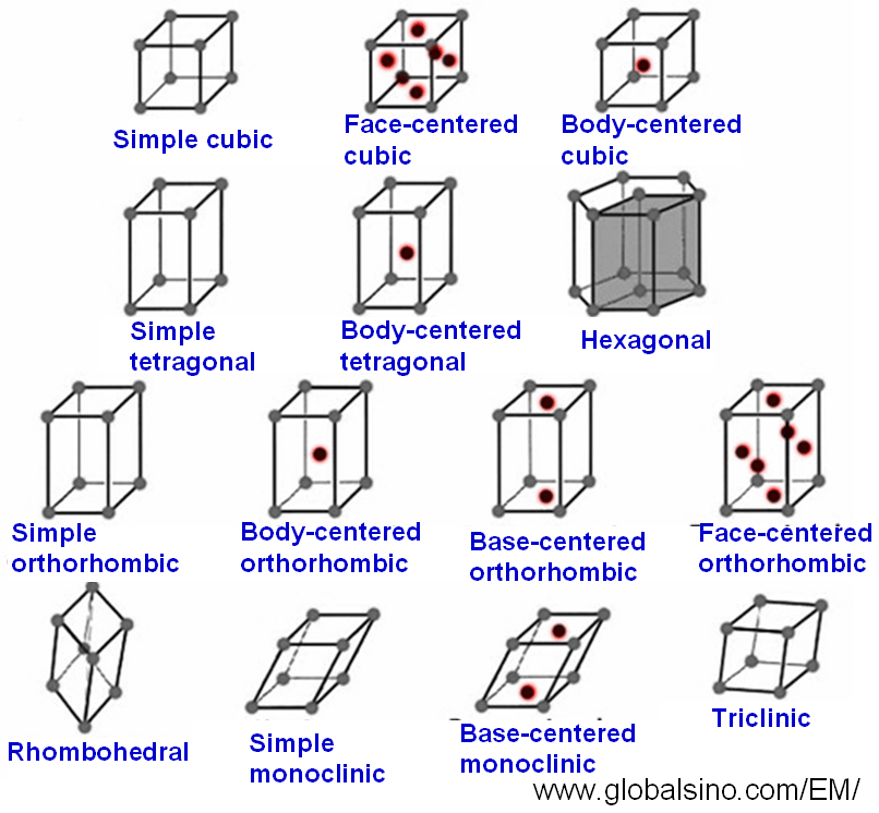
Bravais lattices are a set of 14 distinct lattice structures that describe all possible arrangements of points in space. These lattices can be classified into 7 crystal systems based on their geometric properties:
- Cubic
- Tetragonal
- Orthorhombic
- Rhombohedral
- Hexagonal
- Monoclinic
- Triclinic
Each Bravais lattice is characterized by its lattice points, which are the positions of the atoms, ions, or molecules in the crystal structure.
3. Cubic System
The cubic system is one of the most symmetrical crystal systems, characterized by three equal edge lengths and right angles. It includes three types of lattices:
- Simple Cubic (SC)
- Body-Centered Cubic (BCC)
- Face-Centered Cubic (FCC)
The number of atoms per unit cell varies for each type:
N_{BCC} = 2 \quad (1 \text{ atom at each corner and 1 in the center}) \\
N_{FCC} = 4 \quad (1 \text{ atom at each corner and 1 at the center of each face})
Understanding these structures is crucial for analyzing material properties and behaviors.
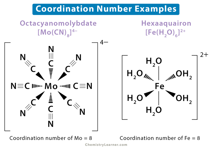
4. Coordination Number
The coordination number is the number of nearest neighbors surrounding an atom in a crystal structure. It reflects how atoms are packed together, influencing the physical properties of the material. The coordination numbers for the cubic system are:
- SC: 6
- BCC: 8
- FCC: 12
5. Atomic Radius and Packing Density
The atomic radius is defined as half the distance between the nuclei of two adjacent atoms in a crystal. It is a crucial parameter in determining the packing density of a crystal, which is the fraction of volume in a crystal structure that is occupied by the atoms. The formula for packing density (\(PD\)) is given by:
This relationship shows how tightly atoms are packed in a crystal structure, affecting properties like density, hardness, and thermal conductivity.
6. Relation between Lattice Constant and Density
The lattice constant is the physical dimension of the unit cell, usually represented as \(a\) for cubic systems. The density (\(ρ\)) of a crystal can be related to the lattice constant and the number of atoms per unit cell (\(N\)) by the following formula:
Where:
- A = Atomic mass
- V_{cell} = Volume of the unit cell (\(a^3\) for cubic cells)
- N_A = Avogadro’s number
This equation highlights how the arrangement of atoms within the lattice affects the overall density of the material.
7. Lattice Planes and Miller Indices
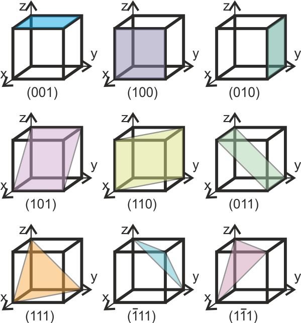
Lattice planes are imaginary planes that pass through lattice points in a crystal. The orientation of these planes is defined using Miller indices, which are a notation system that identifies planes in a crystal lattice. Miller indices \((hkl)\) are determined as follows:
- Identify the intercepts of the plane with the crystal axes.
- Take the reciprocal of these intercepts.
- Clear fractions and reduce to the smallest integer values.
For example, the Miller indices for a plane intercepting the x, y, and z axes at 1, 2, and 3 can be represented as:
8. X-ray Diffraction
X-ray diffraction is a technique used to study the crystal structure of materials. When X-rays are directed at a crystal, they interact with the electrons surrounding the atoms, leading to constructive and destructive interference, which produces a diffraction pattern. The key equation governing X-ray diffraction is Bragg’s law:
Where:
- n = Order of the reflection
- λ = Wavelength of the X-ray
- d = Distance between lattice planes
- θ = Angle of incidence
Bragg’s law is fundamental in determining the crystal structure by analyzing the angles and intensities of the diffracted beams.

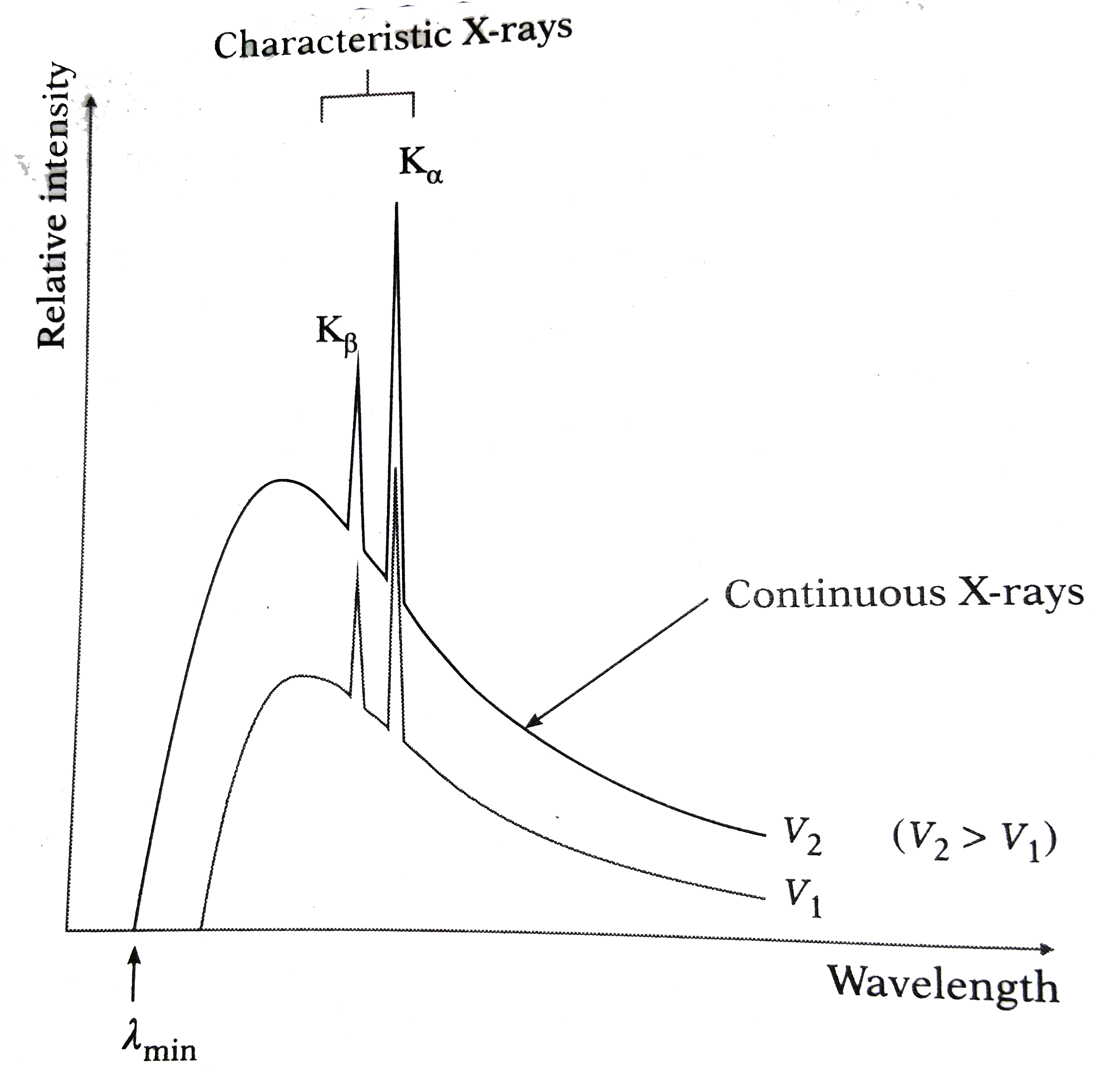
9. Line and Continuous Spectrum of X-ray
The X-ray spectrum can be classified into two types: line spectrum and continuous spectrum. The line spectrum arises from the electronic transitions in atoms, resulting in discrete wavelengths. Conversely, the continuous spectrum (Bremsstrahlung) is produced when high-energy electrons are decelerated upon interacting with matter, resulting in a broad range of wavelengths.
10. Introduction to Maxwell’s Equations
Maxwell’s equations describe the fundamentals of electrodynamics, linking electric and magnetic fields. The four equations are:
- Gauss’s Law: Relates electric fields to charge distributions.
- Gauss’s Law for Magnetism: States that there are no magnetic monopoles.
- Faraday’s Law of Induction: Describes how a changing magnetic field induces an electric field.
- Maxwell-Ampère Law: Relates magnetic fields to electric currents and changing electric fields.
These equations are the foundation of classical electrodynamics, optics, and electric circuits, providing a comprehensive framework for understanding electromagnetic phenomena.
Unit V: Magnetic, Superconducting, and Semiconducting Materials
1. Types of Magnetic Materials
Magnetic materials can be categorized based on their response to an external magnetic field. The primary types include:
Diamagnetic Materials
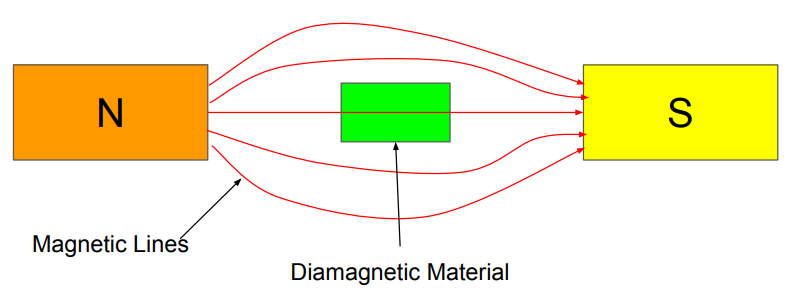
Diamagnetic materials have a very weak and negative response to external magnetic fields. They are characterized by the absence of unpaired electrons, resulting in no permanent magnetic moment. When exposed to a magnetic field, they develop a small magnetic moment in the opposite direction.
Example: Bismuth, Copper.
Paramagnetic Materials
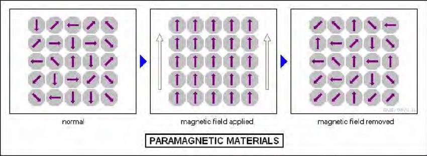
Paramagnetic materials have unpaired electrons, giving them a weak positive susceptibility to magnetic fields. They align with the external field but lose their magnetization once the field is removed. The degree of magnetization is proportional to the field strength.
Example: Aluminum, Platinum.
Ferromagnetic Materials
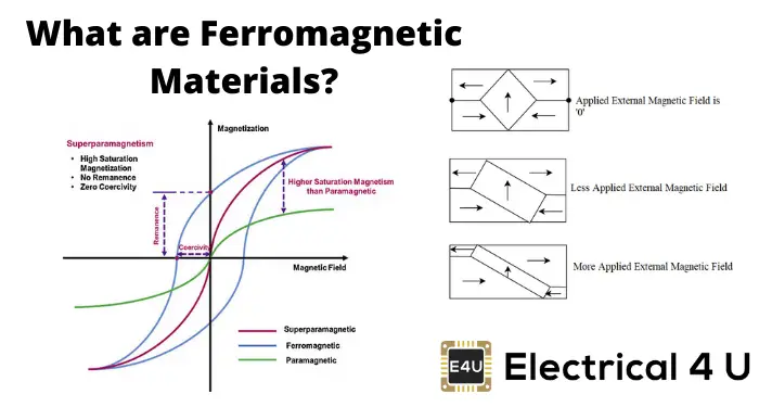
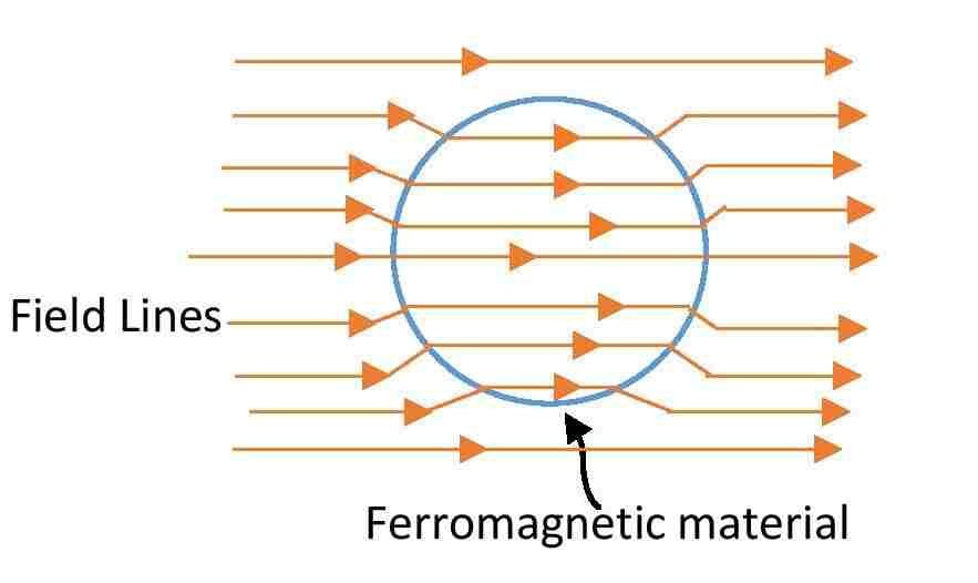
Ferromagnetic materials exhibit strong magnetic properties and retain their magnetization even after the external magnetic field is removed. They have a high degree of magnetic permeability and are characterized by domains that align in the direction of the magnetic field.
Example: Iron, Cobalt, Nickel.
2. B-H Curve
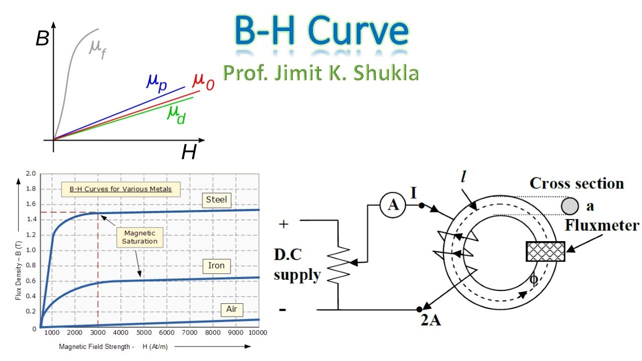
The B-H curve (magnetic hysteresis loop) illustrates the relationship between the magnetic field strength (H) and magnetic flux density (B) in ferromagnetic materials. The curve shows how the material responds to increasing and decreasing magnetic fields.
The main regions of the B-H curve include:
- Initial Magnetization Curve: The initial increase in B with H.
- Saturation: The point at which increasing H no longer increases B significantly.
- Remanence (Br): The remaining magnetization when H is zero.
- Coercivity (Hc): The required H to reduce B to zero.
B_{r} = \text{Remanent flux density}
3. Superconductivity
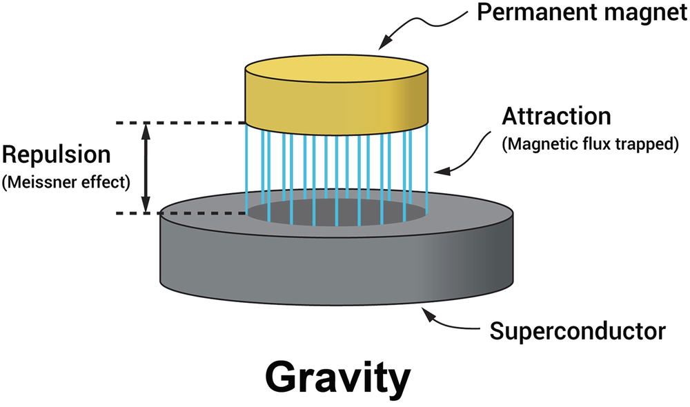
Superconductivity is a phenomenon where a material exhibits zero electrical resistance below a critical temperature (Tc). This results in the expulsion of magnetic fields (Meissner effect), allowing superconductors to exhibit unique behaviors like levitation.
Types of Superconductors
Superconductors can be classified into two main types:
- Type I Superconductors: These materials exhibit superconductivity below a critical magnetic field and completely expel magnetic fields (Meissner effect).
- Type II Superconductors: These materials can allow magnetic fields to penetrate up to a certain limit while still exhibiting superconductivity. They are used in practical applications due to their higher critical fields.
Meissner Effect
The Meissner effect is the expulsion of magnetic fields from a superconductor as it transitions into the superconducting state. This effect is crucial as it allows superconductors to exhibit perfect diamagnetism, enabling applications like magnetic levitation.
Properties and Applications of Superconductors
Superconductors have unique properties such as:
- Zero electrical resistance
- Perfect diamagnetism (Meissner effect)
- High current-carrying capacity
These properties lead to applications in:
- Magnetic levitation trains
- Medical imaging (MRI)
- Particle accelerators
4. Band Theory of Solids
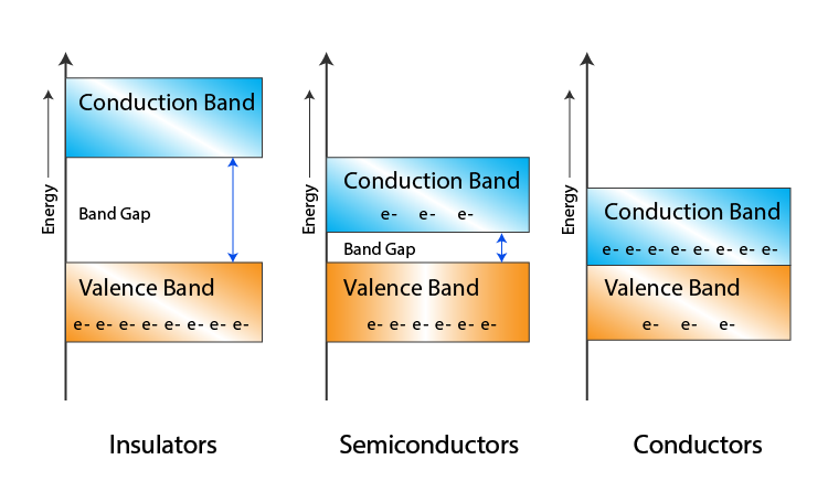
The band theory explains the electronic structure of solids in terms of energy bands. It distinguishes between conductors, semiconductors, and insulators based on the band gap energy:
- Conductors: No band gap; electrons can move freely.
- Semiconductors: Small band gap (0.1 eV – 2 eV); conductivity increases with temperature.
- Insulators: Large band gap (> 2 eV); very low conductivity.
5. Conductivity of Semiconductors
The conductivity (\(σ\)) of semiconductors is influenced by the presence of charge carriers (electrons and holes). The relationship can be described by the formula:
Where:
- σ = Conductivity
- q = Charge of an electron
- n = Concentration of electrons
- p = Concentration of holes
The ability of semiconductors to conduct electricity can be enhanced through doping, which introduces additional charge carriers.
6. Hall Effect
The Hall effect occurs when a magnetic field is applied perpendicular to the flow of current in a conductor or semiconductor, resulting in a voltage difference (Hall voltage) across the material. The Hall voltage (\(V_H\)) can be described by the formula:
Where:
- I = Current
- B = Magnetic field strength
- n = Charge carrier density
- e = Charge of an electron</li
- t = Thickness of the conductor
The Hall effect is widely used in sensors and to determine the type of charge carriers in semiconductors.
Expected Outcome:
1.The student will be able to understand Engineering problems based on the
principle of Oscillation, Ultrasonics, Optics, Laser, Fibre optics, Nuclear physics,
Quantum mechanics.
2.The student will be able to understand Fundamental of Electrodynamics,
Semiconductor, Dielectric, Magnetic and Superconducting materials which forms
the base of many modern devices andtechnologies.
Text books:
1. Engineering Physics M.N.Avadhanulu and P.G. Kshirsagar. S.Chandand
Company LTD.
2. Engineering Physics – Dr. L. N. Singh. SynergyKnowledgeware-Mumbai.
3. Engineering Physics-R.K. Gaur and S. L.Gupta.Dhanpat Rai
Publications Pvt. Ltd.-NewDelhi.
4. Fundamental of Physics – Halliday and Resnik. Willey EasternLimited.
Reference books:
1. Introduction to Electrodynamics –David R.Griffiths.
2. Concept of Modern Physics – Arthur Beizer.TataMcGraw-HillPublishing
Company Limited.
3. Optics – Ajoy Ghatak, MacGraw Hill Education (India) Pvt.Ltd.
4. Science of Engineering Materials- C.M. Srivastava and C. Srinivasan. New
Age InternationalPvt.Ltd.
5. Solid State Physics – A.J. Dekker. McMillan India–Limited.
6. The Feynman Lectures on Physics VolI,II,III.
7. Introduction to solid state physics – Charles Kittel. John Willey andSons
