Sheet Metal Engineering
Unit 1: Momentum Equation and its Applications
1. Impulse Momentum Principle
The impulse-momentum principle states that the change in momentum of a system is equal to the impulse applied to it. The momentum equation can be derived as:
Impulse = Change in Momentum
F * Δt = m * Δv
1.1 Applications
- Force analysis on flat and inclined plates.
- Impact of fluids on stationary and moving plates.
2. Fixed and Moving Flat Inclined Plates
When a fluid strikes flat inclined plates, the force exerted by the fluid on the plate depends on its velocity and angle of inclination. For moving plates, the relative velocity is considered to calculate the momentum change.
2.1 Curved Vanes
For curved vanes, the velocity components are resolved along the vane surface. The force calculation is based on the deflection of the fluid by the curved surface.
2.2 Series of Plates and Vanes
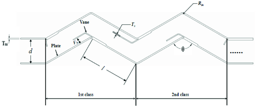
A series of plates or vanes can be used in applications like turbines and pumps. The total momentum change in the system is determined by analyzing the fluid’s interaction with each element in the series.
3. Velocity Triangle and Analysis
In hydrodynamic machines like turbines, velocity triangles are used to analyze the velocities of the fluid entering and exiting the vanes or blades. The velocity triangle helps in determining the work done and efficiency of the machine.

4. Water Wheels
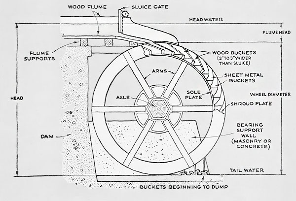
Water wheels convert the kinetic energy of flowing water into mechanical energy. The momentum equation helps in calculating the force exerted by the water on the wheel, which determines its power output.
5. Hydrodynamic Machines
Hydrodynamic machines are devices that convert fluid energy into mechanical work, such as pumps and turbines. Their performance is governed by fundamental fluid dynamics principles.
5.1 Classification
- Centrifugal Pumps: Uses rotational kinetic energy to move fluids.
- Axial Flow Pumps: Fluid moves parallel to the axis of rotation.
- Turbines: Convert fluid energy into rotational energy.
6. General Theory and Fundamental Equations
The general theory of hydrodynamic machines involves energy transfer between the fluid and the moving parts. The fundamental equation governing this energy transfer is Euler’s equation for turbomachines:
ΔH = (U₁Vw₁ – U₂Vw₂) / g
7. Centrifugal Head and Euler’s Equation
Centrifugal head is the energy imparted to a fluid by a rotating impeller in a centrifugal pump. Euler’s equation describes the relationship between fluid velocity, angular velocity, and energy transfer.
8. Degree of Reaction
The degree of reaction is a measure of the energy exchange between the fluid and the rotating component of a hydrodynamic machine. It is defined as the ratio of static pressure energy change to the total energy change in the fluid.
9. Head on Machine and Efficiencies
The head on a hydrodynamic machine refers to the total height of fluid above the machine that is converted into pressure or velocity. Efficiencies are categorized into:
- Mechanical Efficiency: Ratio of mechanical output to input.
- Hydraulic Efficiency: Ratio of useful fluid power to the power imparted by the machine.
- Overall Efficiency: Product of mechanical and hydraulic efficiencies.
10. Condition for Maximum Hydraulic Efficiency
The condition for maximum hydraulic efficiency is achieved when the fluid velocity relative to the vane is optimized. This ensures the maximum amount of energy is transferred from the fluid to the machine or vice versa.
Unit 2: Impulse and Reaction Turbines
1. Impulse Principle
Impulse turbines work on the principle of converting the kinetic energy of a jet of water into mechanical energy. In these turbines, the high-velocity jet strikes the blades of the turbine, creating an impulse that rotates the wheel.
2. Construction of Pelton Wheel
The Pelton wheel is the most commonly used impulse turbine. It consists of a rotor with multiple buckets mounted along the circumference. Water jets are directed towards these buckets, causing the wheel to rotate.

2.1 Velocity Diagrams and Analysis
Velocity diagrams help in understanding the energy conversion process in Pelton wheels. The inlet and outlet velocities of the fluid and the relative velocities of the bucket are considered in the analysis.
2.2 Number of Buckets, Jets, Speed Ratio, and Jet Ratio
- Number of Buckets: The number of buckets depends on the size of the Pelton wheel and the flow rate of water. It is generally optimized for efficient energy transfer.
- Jets: The number of jets depends on the size of the turbine and the flow rate required. More jets increase the power output.
- Speed Ratio: The speed ratio is the ratio of the peripheral speed of the bucket to the velocity of the water jet.
- Jet Ratio: The jet ratio is the ratio of the diameter of the Pelton wheel to the diameter of the water jet.
3. Reaction Turbines
Unlike impulse turbines, reaction turbines use both the pressure and kinetic energy of the fluid. The fluid changes pressure as it passes through the turbine rotor, and the energy transfer happens due to the reaction force of the fluid.
3.1 Constructional Details of Francis, Kaplan, Propeller, and Deciaz Turbines
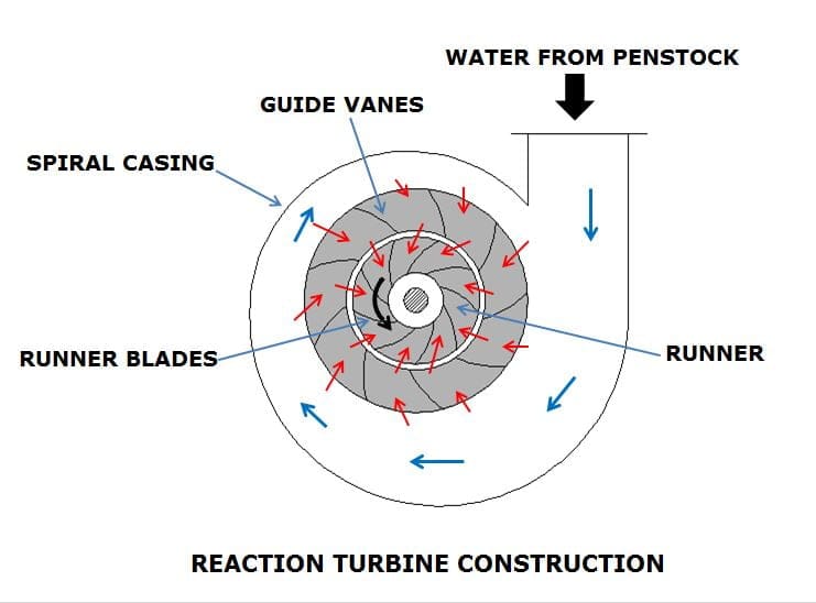
- Francis Turbine: A mixed flow turbine where water enters radially and exits axially. It has a spiral casing and guide vanes that control the flow of water to the rotor blades.
- Kaplan Turbine: A propeller-type turbine where water flows axially. It has adjustable blades to accommodate different flow conditions, which makes it efficient for varying loads.
- Propeller Turbine: Similar to Kaplan, but with fixed blades. It is suitable for low head and high flow applications.
- Deciaz Turbine: A specialized type of reaction turbine designed for small hydropower applications with moderate flow rates.
4. Draft Tube Types
A draft tube is a device that recovers the kinetic energy from the fluid exiting the turbine. It reduces the exit velocity, allowing the turbine to operate at low pressure. There are several types of draft tubes:
- Conical Draft Tube: Converging at the top and diverging at the bottom to recover pressure effectively.
- Elbow Draft Tube: Used when space constraints require a bend in the exit path of the fluid.
- Moody Spreading Tube: A special type of draft tube designed to reduce cavitation.
5. Efficiencies in Turbines
- Hydraulic Efficiency: The ratio of the energy imparted to the rotor to the energy available from the fluid.
- Mechanical Efficiency: The ratio of the mechanical energy output to the mechanical input, considering friction losses.
- Overall Efficiency: The product of hydraulic and mechanical efficiencies, representing the total efficiency of the turbine system.
6. Cavitation
Cavitation is the formation of vapor bubbles in a fluid due to a drop in pressure below the vapor pressure. In turbines, cavitation can cause damage to the blades and reduce the efficiency of the machine.
To prevent cavitation, turbines are designed to maintain a minimum pressure throughout the system, and draft tubes are employed to recover energy from the fluid.
Unit 3: Governing of Turbines
1. Methods of Governing
Governing of turbines refers to the process of controlling the speed and power output of the turbine in response to varying load conditions. Different methods of governing are used for different types of turbines to maintain stability and efficiency.
1.1 Throttle Governing
In throttle governing, the flow of steam or water to the turbine is controlled by regulating the throttle valve. This method is commonly used in steam turbines.
1.2 Nozzle Control Governing
Nozzle control governing is typically used in impulse turbines. The flow of steam is controlled by regulating the number of active nozzles, allowing for fine control of turbine speed.
1.3 Bypass Governing
In bypass governing, a portion of the steam or water is allowed to bypass the turbine during periods of low load, maintaining turbine speed without wasting energy.
1.4 Flow Regulation in Hydraulic Turbines
In hydraulic turbines, governing is achieved by controlling the flow of water through the turbine using wicket gates or guide vanes. This adjusts the turbine’s speed according to the load.
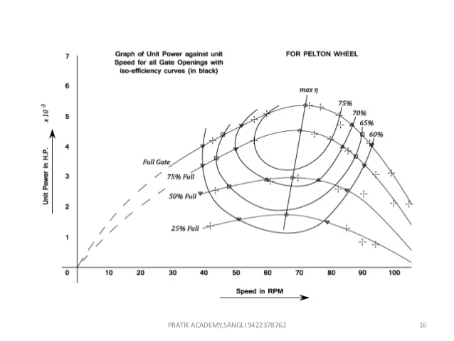
2. Performance Characteristics
Performance characteristics of turbines are determined by their efficiency, output, and response to varying load conditions. The main characteristics include:
- Efficiency: The ratio of useful work done by the turbine to the energy input, expressed as a percentage.
- Power Output: The actual amount of mechanical power produced by the turbine.
- Speed Regulation: The ability of the turbine to maintain a constant speed under varying loads.
3. Safety Devices
Turbines are equipped with several safety devices to protect against over-speeding and other potential hazards. These include:
- Over-speed Governor: Automatically shuts down the turbine if its speed exceeds safe limits.
- Pressure Relief Valves: Used to relieve excessive pressure in the turbine system.
- Emergency Stop Valve: Quickly shuts off the flow of steam or water to the turbine in case of an emergency.
4. Selection of Turbines
Selection of a turbine depends on several factors, including the type of fluid, head, flow rate, and the required output. The following types of turbines are commonly used:
- Pelton Turbine: Suitable for high head and low flow conditions.
- Francis Turbine: Best suited for medium head and flow rate applications.
- Kaplan Turbine: Used for low head and high flow rate conditions.
- Steam Turbines: Used in power plants for generating electricity from steam.
5. Unit Quantities
Unit quantities are dimensionless parameters used to compare the performance of different turbines operating under similar conditions. These quantities help in analyzing turbine efficiency and scaling model test results to full-scale turbines. Important unit quantities include:
- Unit Power (Pu): Power output at unit speed and head.
- Unit Speed (Nu): Speed of the turbine operating under unit head.
- Unit Flow (Qu): Flow rate under unit head conditions.
6. Specific Speed
Specific speed (Ns) is a dimensionless parameter that characterizes the type and performance of a turbine. It is used for turbine selection and performance analysis. Specific speed is defined as:
Where:
- N = Rotational speed of the turbine (RPM)
- P = Power output (kW)
- H = Head (m)
The value of specific speed helps determine the most suitable turbine for a given application:
- Low Specific Speed: For Pelton turbines, used in high-head, low-flow applications.
- Medium Specific Speed: For Francis turbines, used in medium-head and flow conditions.
- High Specific Speed: For Kaplan turbines, used in low-head, high-flow conditions.
7. Principles of Similarity and Model Testing
The principle of similarity states that geometrically similar turbines will have similar performance if their specific speeds are the same. This principle is used in model testing, where a smaller model of the turbine is tested under controlled conditions to predict the performance of the full-scale turbine.
Key conditions for similarity are:
- Geometric Similarity: The model and prototype must have the same shape and proportions.
- Kinematic Similarity: Velocities at corresponding points must be proportional.
- Dynamic Similarity: Forces in the model and prototype must be proportional.
Model testing allows for accurate prediction of full-scale turbine performance, helping in design optimization and selection.
Unit 4: Centrifugal Pump
1. Construction and Classification
A centrifugal pump is a machine used for the movement of fluids by converting mechanical energy into hydraulic energy. It consists of the following major components:
- Impeller: The rotating part that converts the mechanical energy into hydraulic energy.
- Casing: Encloses the impeller and creates a smooth pathway for fluid to flow.
- Shaft: Connects the impeller to the motor.
- Suction Pipe: Draws fluid from the source into the pump.
- Delivery Pipe: Carries fluid from the pump to the desired location.
Centrifugal pumps can be classified based on various criteria:
- Number of stages: Single-stage or multi-stage pumps.
- Impeller type: Closed, semi-open, or open impeller.
- Flow direction: Radial flow, axial flow, or mixed flow pumps.
2. Terminology Related to Pumps
- Head: The height to which a pump can raise a fluid.
- Flow rate (Q): The volume of fluid pumped per unit time, usually in m3/s or L/min.
- Efficiency: Ratio of useful power output to the power input.
- Discharge: The volume of fluid that is moved by the pump.
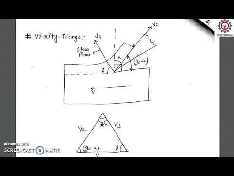
3. Velocity Triangle and Their Analysis
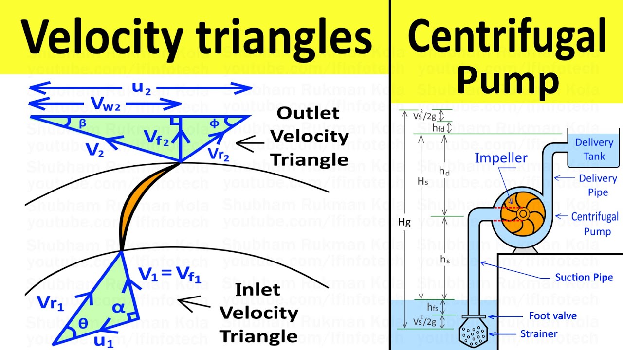
The velocity triangle is used to analyze the flow of fluid through the impeller. The velocity components are:
- Vr: Radial velocity component.
- Vw: Tangential velocity component or whirl velocity.
- Vf: Absolute velocity of the fluid.
These components help in determining the forces acting on the fluid and calculating power consumption, efficiency, and other parameters.
4. Cavitation, NPSH, and Thoma’s Cavitation Factor
Cavitation occurs when the local pressure in the pump falls below the vapor pressure of the liquid, leading to the formation of vapor bubbles. These bubbles collapse when subjected to higher pressure, causing damage to the impeller.
NPSH (Net Positive Suction Head): It is the pressure required at the suction side of the pump to avoid cavitation. It consists of two components:
- NPSHA (Available): The actual pressure available at the suction of the pump.
- NPSHR (Required): The minimum pressure required to avoid cavitation.
Thoma’s Cavitation Factor (σ): It is a dimensionless parameter used to predict cavitation in pumps.
5. Priming and Methods of Priming
Priming is the process of removing air from the pump casing and suction line to ensure the pump is filled with liquid before starting. Common methods of priming include:
- Manual priming by filling the pump casing with liquid.
- Vacuum priming using a vacuum pump to remove air.
- Self-priming pumps that automatically remove air and draw liquid.
6. Specific Speed (Ns)
Specific speed is a dimensionless parameter that indicates the type and performance characteristics of a pump. It is defined as:
Where:
- N = Rotational speed (RPM)
- Q = Flow rate (m3/s)
- H = Head (m)
Specific speed helps in determining the most appropriate pump for a given application. Lower specific speed values are suitable for radial flow pumps, while higher values are better for axial flow pumps.
7. Performance Characteristics
Performance characteristics of a centrifugal pump are represented by the following curves:
- Head vs. Flow rate (H-Q curve): Shows how the head decreases as the flow rate increases.
- Power vs. Flow rate: Indicates how power consumption changes with flow rate.
- Efficiency vs. Flow rate: Efficiency of the pump at various flow rates.
8. Actual Thrust and Its Compensation
During operation, centrifugal pumps experience axial thrust due to pressure differences. Compensation methods include the use of:
- Balancing discs or drums: These balance the axial forces acting on the impeller.
- Thrust bearings: Absorb the remaining unbalanced axial thrust.
9. Troubleshooting Common Issues
- Cavitation: Caused by insufficient NPSH. Solution: Increase suction pressure or reduce pump speed.
- Excessive Vibration: Due to misalignment, wear, or imbalance. Solution: Inspect and align components, replace worn parts.
- Low Discharge Pressure: Due to air leaks or impeller damage. Solution: Check for air leaks and inspect the impeller.
- Overheating: Due to excessive load or friction. Solution: Reduce load, check lubrication.
10. Multistage Pumps
Multistage pumps are used when a single-stage pump cannot provide the required head or pressure. Each stage consists of an impeller that increases the pressure incrementally.
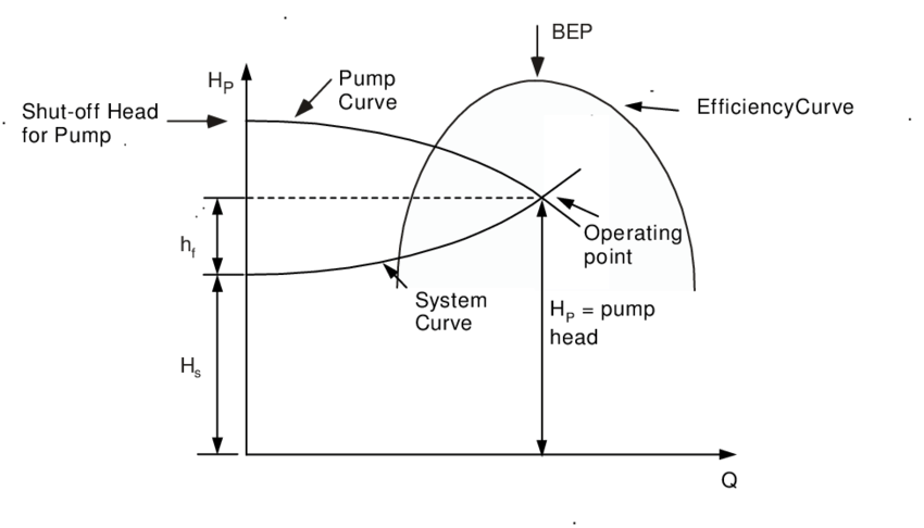
10.1 Pump H-Q Characteristics and System H-Q Characteristics
The head-flow characteristics of the pump (H-Q curve) must match the system’s requirements for efficient operation. System H-Q characteristics represent the relationship between the head required by the system and the flow rate.
10.2 Series and Parallel Operation of Pumps
- Series Operation: Increases the head while maintaining the same flow rate. Used when high pressure is required.
- Parallel Operation: Increases the flow rate while maintaining the same head. Used when high flow is required.
10.3 Systems in Series and Parallel
In practice, pumping systems often involve multiple pumps operating in series or parallel to meet the specific system requirements. Proper matching of pump and system characteristics ensures efficient performance.
11. Principle of Model Testing and Similarity
Model testing is used to predict the performance of full-scale pumps by testing smaller models. The principle of similarity ensures that the model’s performance reflects that of the actual pump when operating under similar conditions.
The key conditions for similarity include:
- Geometric Similarity: The model and prototype must have the same geometric proportions.
- Kinematic Similarity: The velocity distribution must be the same in both model and prototype.
- Dynamic Similarity: The forces acting on the fluid in the model must scale proportionally to those in the prototype.
Unit 5: Special Purpose Pumps
1. Chemical Pumps
Chemical pumps are specifically designed to handle corrosive or hazardous fluids, such as acids, alkalis, and volatile chemicals. They are used in industries like petrochemical, pharmaceutical, and food processing.
Key features:
- Corrosion-resistant materials such as stainless steel, PTFE, or composite materials.
- Leak prevention mechanisms, such as magnetic drive systems or mechanical seals.
- Capability to handle a wide range of temperatures and pressures.
2. Nuclear Pumps
Nuclear pumps are used in nuclear power plants for the transfer of radioactive fluids, reactor cooling, and water circulation. These pumps must meet strict safety and regulatory standards.
Key features:
- High reliability and durability under extreme temperatures and pressures.
- Materials resistant to radiation and corrosion.
- Designed to operate continuously without frequent maintenance.
3. Sewage Pumps
Sewage pumps are used for the transportation of wastewater or sewage. These pumps are designed to handle solids and prevent clogging.
Key features:
- Grinders or cutters to break down solids before pumping.
- Non-clog impellers to prevent blockage.
- Submersible design for use in wet environments like sewage pits or septic tanks.
4. Submersible Deep Well Pumps
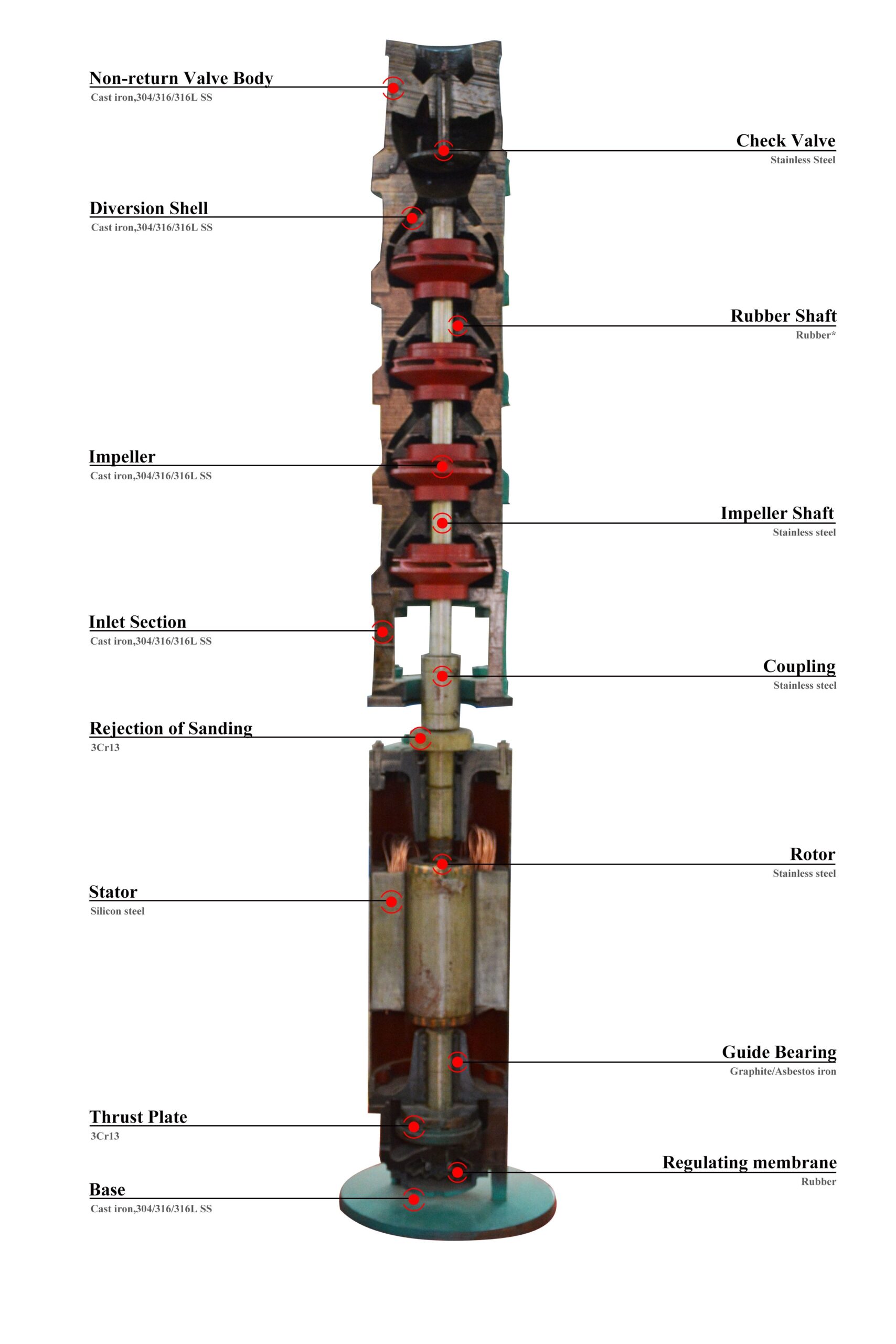
Submersible deep well pumps are used to lift water from deep underground sources, such as wells. These pumps are fully submerged in water and are often used for irrigation, drinking water supply, and industrial applications.
Key features:
- Multiple impellers for high head applications.
- Corrosion-resistant materials for long-term use in harsh environments.
- Compact and efficient design for deep water extraction.
5. Pump Installation and Energy Efficient Pumps
The correct installation of pumps is critical to ensure efficiency and longevity. Proper alignment, foundation support, and connection of suction and discharge pipes are essential for trouble-free operation.
Energy-efficient pumps are designed to minimize energy consumption, reduce operating costs, and lower environmental impact. Features include:
- High-efficiency motors and impellers.
- Variable speed drives (VSDs) to match pump performance with demand.
- Smart control systems for optimizing performance and reducing energy waste.
6. Failure of Pumping System
6.1 Pump Failures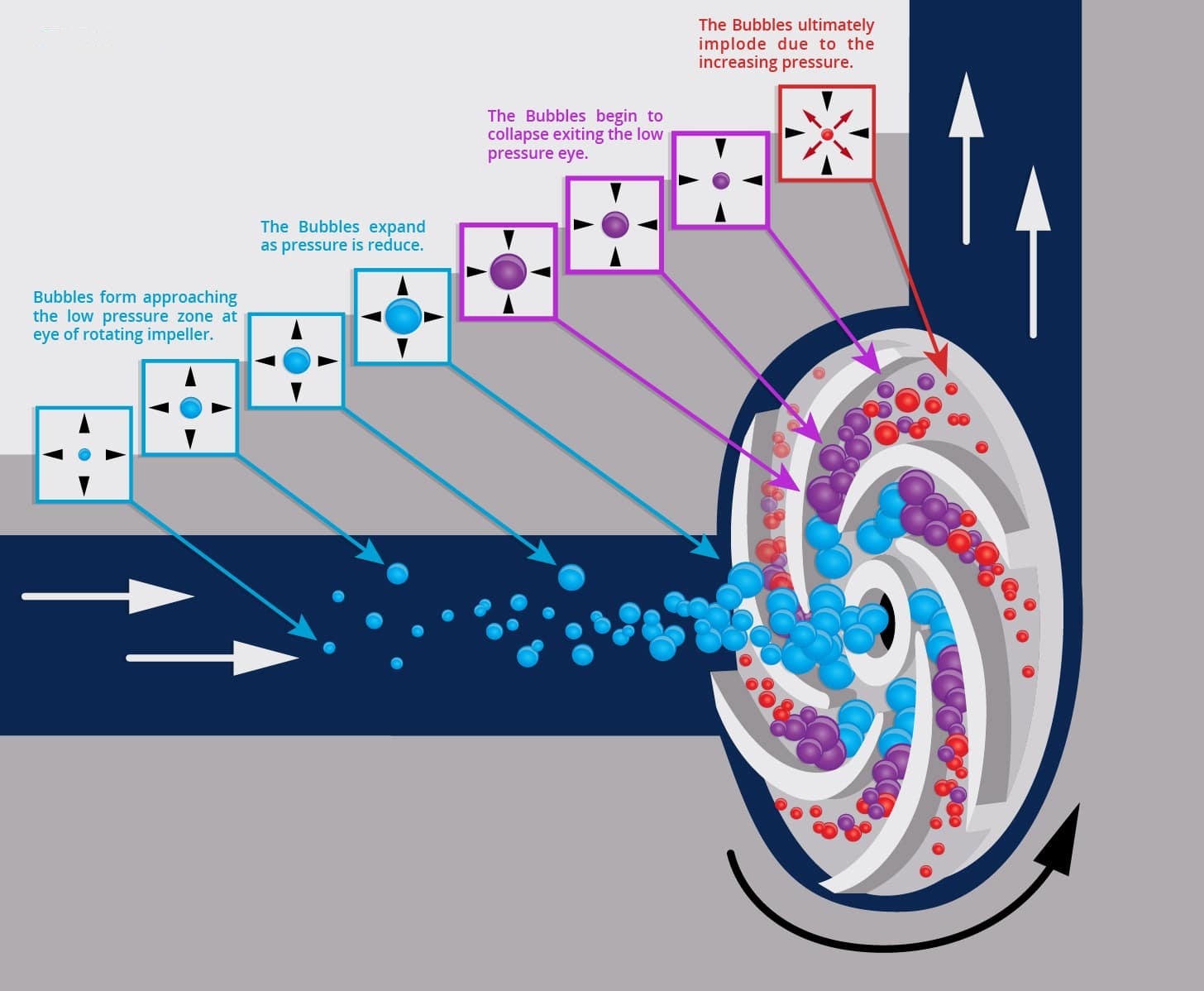
Pump failures can result from various issues, including wear, poor maintenance, or incorrect operation. Common causes of failure include:
- Cavitation: Low suction pressure causes vapor bubbles to form, damaging the impeller.
- Overheating: Lack of cooling or excessive load on the pump.
- Seal Failure: Caused by leakage or improper lubrication.
- Bearings Failure: Excessive vibration or lack of lubrication.
6.2 Remedies
- Cavitation: Increase suction head, reduce pump speed, or use a larger suction pipe.
- Overheating: Check coolant levels, reduce the operating load, and ensure proper ventilation.
- Seal Failure: Regular maintenance of seals, proper lubrication, and use of high-quality materials.
- Bearings Failure: Lubricate bearings regularly, monitor vibration levels, and replace worn bearings.
6.3 Source Failure and Troubleshooting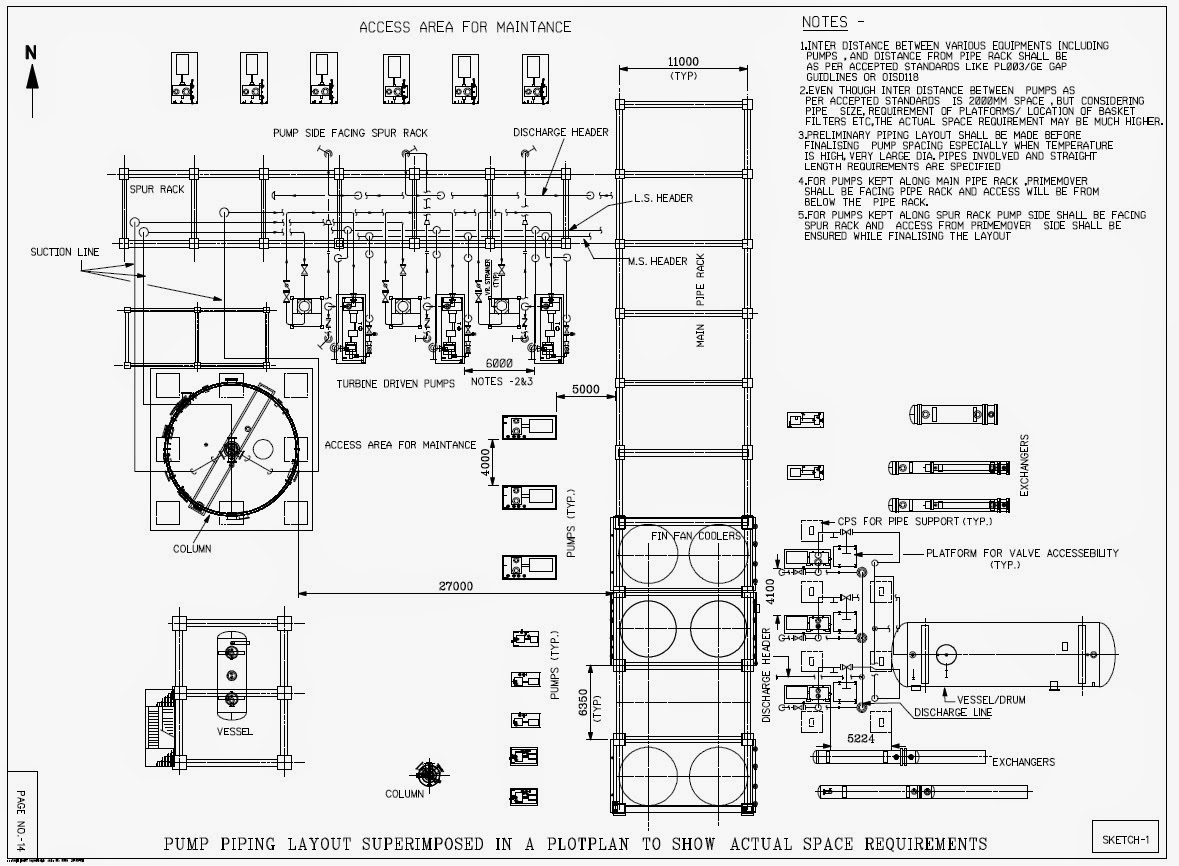
Source failure refers to problems originating from external factors such as low water supply, power issues, or incorrect system design.
Troubleshooting involves identifying and addressing problems in the system:
- Poor Performance: Check pump sizing, impeller condition, and system configuration.
- Vibration and Noise: Inspect for misalignment, unbalanced impellers, or worn bearings.
- Leakage: Check seals, pipe connections, and gaskets for wear and damage.
7. Miscellaneous Pumps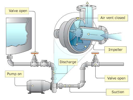
7.1 Reciprocating Pump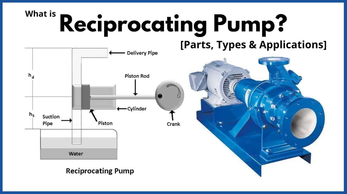
A reciprocating pump uses a piston or plunger to move fluid in a cyclic manner. These pumps are often used in applications where high pressure is needed, such as oil wells or hydraulic systems.
7.2 Gear Pump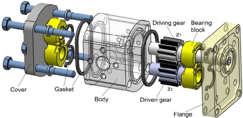
Gear pumps are used to transfer viscous fluids like oil or chemical slurries. They consist of interlocking gears that move fluid as the gears rotate. Gear pumps are highly efficient and durable.
7.3 Vane Pump
Vane pumps use rotating vanes that slide in and out of a rotor, creating chambers that move fluid. These pumps are widely used in automotive applications and hydraulic systems.
7.4 Lobe Pump
Lobe pumps use two or more lobed rotors that rotate in opposite directions to move fluid. These pumps are common in food processing and pharmaceutical industries due to their gentle handling of fluids.
8. Application Fields of Miscellaneous Pumps
The following table summarizes the typical application fields of miscellaneous pumps:
| Pump Type | Application Field |
|---|---|
| Reciprocating Pump | Hydraulic systems, high-pressure cleaning, oil wells |
| Gear Pump | Oil transfer, chemical processes, lubrication systems |
| Vane Pump | Power steering, hydraulic systems, fuel pumps |
| Lobe Pump | Food processing, pharmaceuticals, cosmetic manufacturing |
Texts:
1. P. N. Modi, S. M. Seth, “Hydraulics and Fluid Mechanics including Hydraulic Machines”,
Standard Book House, Rajsons Publications Pvt. Ltd., 20th edition.
2. R. K. Bansal, “A Text Book of Fluid Mechanics and Hydraulic Machines”, Lakshmi
Publications Pvt. Ltd., 9th edition.
