Heat Transfer
Unit 1: Introduction to Heat Transfer
1. Heat Transfer Mechanisms
Heat transfer is the process of energy moving from a hotter region to a cooler one. The main mechanisms of heat transfer are:
- Conduction: Transfer of heat through a solid material.
- Convection: Transfer of heat by fluid motion.
- Radiation: Transfer of heat through electromagnetic waves.
2. Conduction Heat Transfer
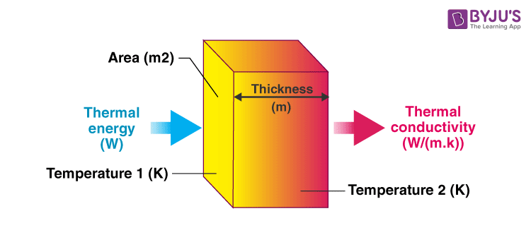
Conduction occurs when heat flows through a material without the movement of the material itself. It is governed by Fourier’s Law.
- q: Heat transfer rate (W)
- k: Thermal conductivity (W/m·K)
- A: Cross-sectional area (m²)
- dT/dx: Temperature gradient (K/m)
2.1 Thermal Conductivity
Thermal conductivity (k) is a measure of a material’s ability to conduct heat. Higher thermal conductivity means the material conducts heat better.
3. Convection Heat Transfer
Convection involves the movement of fluids to transfer heat. It can be forced (by external means) or natural (due to buoyancy effects).
- h: Convective heat transfer coefficient (W/m²·K)
- T_s: Surface temperature (K)
- T_∞: Fluid temperature far from the surface (K)
3.1 Types of Convection
- Forced Convection: Occurs when fluid motion is induced by external means such as fans or pumps.
- Natural Convection: Driven by buoyancy forces due to temperature differences.
4. Radiation Heat Transfer
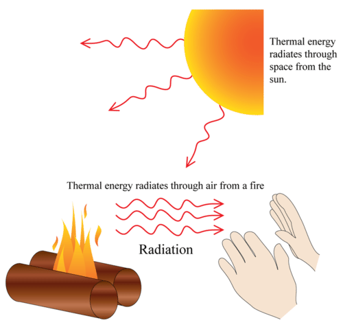
Radiation is the transfer of heat through electromagnetic waves. All bodies emit radiation depending on their temperature.
- ε: Emissivity (dimensionless)
- σ: Stefan-Boltzmann constant (5.67 × 10⁻⁸ W/m²·K⁴)
- T_s: Surface temperature (K)
- T_∞: Ambient temperature (K)
5. Steady State Conduction
Steady-state conduction means that the temperature distribution does not change over time. We can analyze different geometries for steady-state conduction:
5.1 General Heat Conduction Equation
The general heat conduction equation in three dimensions is:
- T: Temperature (K)
- α: Thermal diffusivity (m²/s)
- ∇²T: Laplacian of temperature
5.2 One-Dimensional Steady-State Conduction
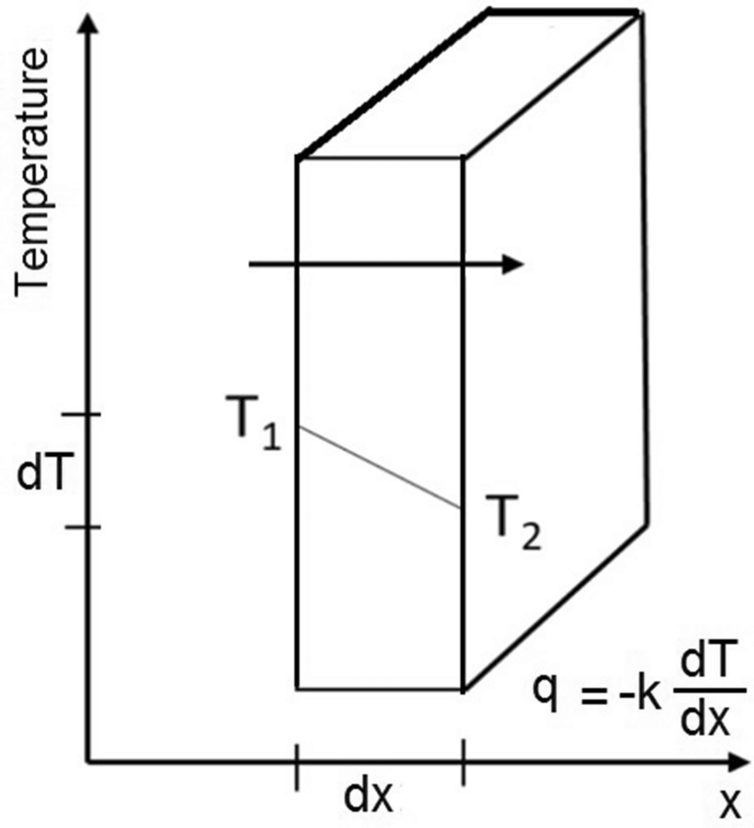
In one-dimensional steady-state conduction, the heat transfer can be analyzed through different geometrical shapes:
5.2.1 Slab
- L: Thickness of the slab (m)
5.2.2 Cylinder
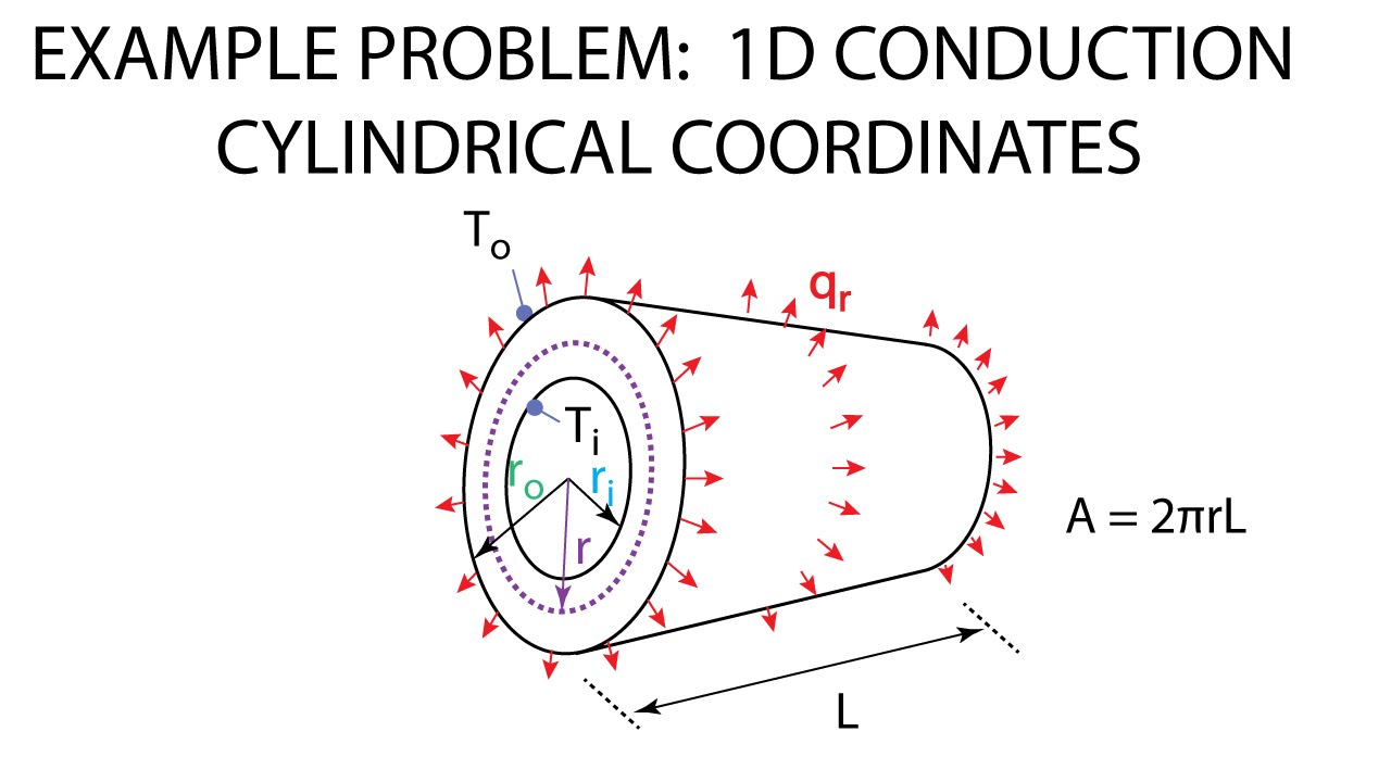
- r1: Inner radius (m)
- r2: Outer radius (m)
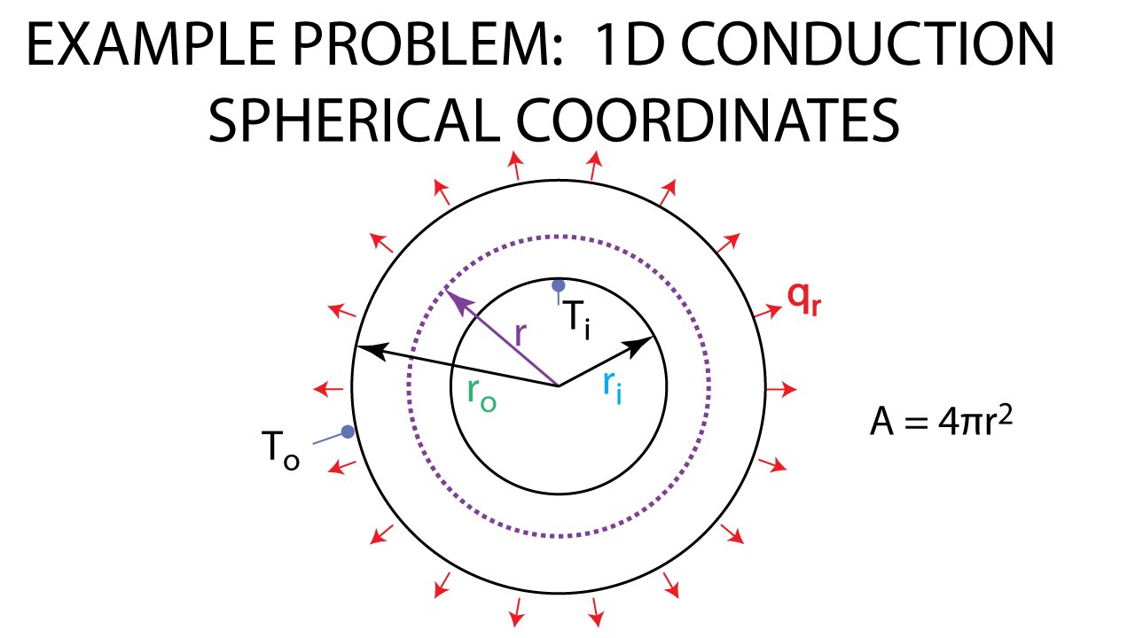
5.2.3 Sphere
- R: Radius of the sphere (m)
5.3 Composite Systems
In composite systems, multiple materials are layered or combined. The overall thermal resistance is the sum of the resistances of each layer:
- R: Thermal resistance (K/W)
Unit 2: Overall Heat Transfer and Extended Surfaces
1. Thermal Contact Resistance
Thermal contact resistance, also known as thermal interface resistance, is the resistance to heat flow across the interface of two materials. It can be significant when materials are in contact with each other but have different thermal conductivities.
1.1 Formula for Thermal Contact Resistance
The thermal contact resistance (Rc) can be calculated using the formula:
Where:
- ΔT = Temperature difference across the contact
- Q = Heat flux through the contact
Understanding and minimizing thermal contact resistance is crucial for efficient thermal management in electronic devices and heat exchangers.

Figure 1: Thermal Contact Resistance in a Heat Exchanger
2. Critical Radius of Insulation
The critical radius of insulation is the radius at which the thermal resistance is maximized for a cylindrical or spherical object. This concept is essential in designing insulation systems to ensure optimal thermal performance.
2.1 Formula for Critical Radius of Insulation
The critical radius (rc) for cylindrical insulation is given by:
Where:
- k = Thermal conductivity of the insulation material
- h = Heat transfer coefficient of the surrounding fluid
For spherical insulation, the formula is slightly different. The critical radius determines the optimal thickness of insulation to minimize heat loss.
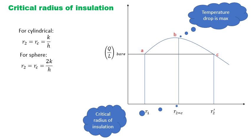
Figure 2: Critical Radius of Insulation for Cylindrical and Spherical Bodies
3. Electrical Analogy
The electrical analogy is a method used to simplify heat transfer problems by drawing parallels between electrical circuits and thermal systems. This approach helps in understanding and solving complex heat transfer problems.
3.1 Basic Analogies
In the electrical analogy:
- Temperature Difference is analogous to Voltage
- Heat Flux is analogous to Current
- Thermal Resistance is analogous to Electrical Resistance
Using these analogies, complex heat transfer problems can be solved by treating them as electrical circuits with resistors, capacitors, and voltage sources.
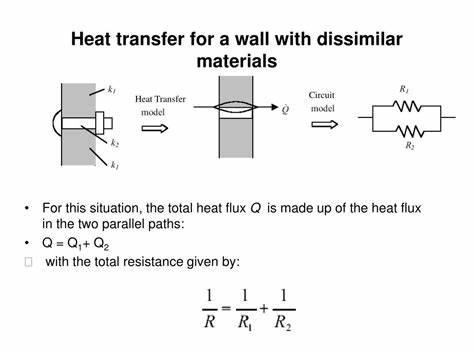
Figure 3: Electrical Analogy in Heat Transfer
4. Overall Heat Transfer Coefficient
The overall heat transfer coefficient (U) quantifies the rate of heat transfer through a combination of conductive, convective, and sometimes radiative heat transfer processes.
4.1 Formula for Overall Heat Transfer Coefficient
The overall heat transfer coefficient is given by:
Where:
- Rtotal = Total thermal resistance, which includes:
- Rcond = Conductive resistance
- Rconv1 = Convective resistance on one side
- Rconv2 = Convective resistance on the other side
The formula can be expanded as:
By calculating the overall heat transfer coefficient, engineers can assess the efficiency of heat exchangers, insulation, and other thermal systems.
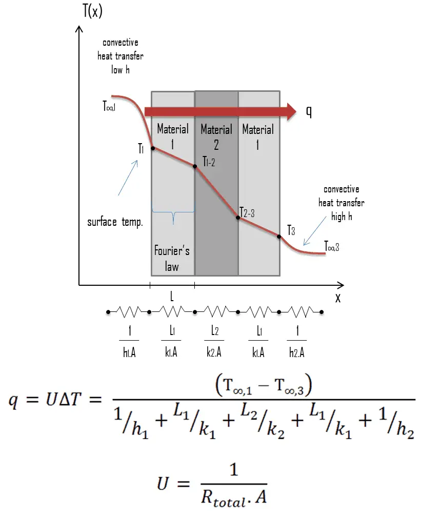
Figure 4: Calculation of Overall Heat Transfer Coefficient
5. Heat Sources Systems
Heat sources systems are designed to transfer heat from a source to a target system effectively. These systems are used in various applications, including HVAC systems, industrial processes, and energy systems.
5.1 Key Components
- Heat Sources: Devices that generate heat, such as boilers, furnaces, and electrical heaters.
- Heat Exchangers: Components that transfer heat between two fluids, often used to maximize energy efficiency.
- Distribution Systems: Systems for transporting heated fluids to the target locations, including pipes and ducts.
Efficient design and operation of heat sources systems are crucial for energy savings and effective thermal management.
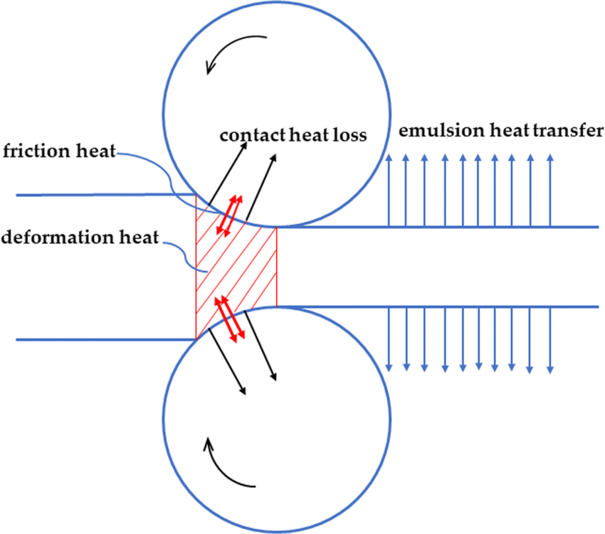
Figure 5: Heat Sources Systems Layout
6. Variable Thermal Conductivity
Variable thermal conductivity refers to materials whose thermal conductivity changes with temperature or other conditions. This concept is essential for designing thermal systems that operate under varying conditions.
6.1 Modeling Variable Thermal Conductivity
When dealing with materials with variable thermal conductivity, the thermal conductivity (k) can be expressed as a function of temperature (T):
Where:
- k(T) = Thermal conductivity at temperature T
- k0 = Thermal conductivity at reference temperature T0
- α = Temperature coefficient of thermal conductivity
- T = Current temperature
- T0 = Reference temperature
This model helps in predicting the thermal performance of materials under different operating conditions.
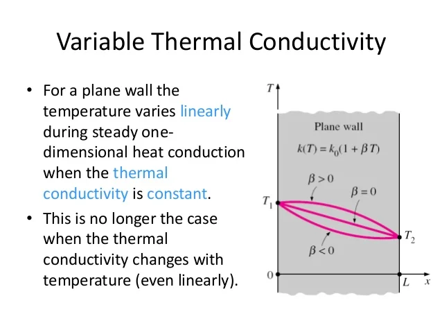
Figure 6: Variable Thermal Conductivity with Temperature
7. Extended Surfaces
Extended surfaces, or fins, are used to increase the surface area for heat transfer. They are commonly used in heat exchangers, radiators, and other thermal systems to enhance heat dissipation.
7.1 Types of Extended Surfaces
- Straight Fins: Simple fins that extend in a straight line from a surface.
- Pin Fins: Cylindrical fins that are used in high heat flux applications.
- Annular Fins: Fins that are used in cylindrical geometries, such as in pipe heat exchangers.
The choice of fin type depends on the specific application and required heat transfer performance.
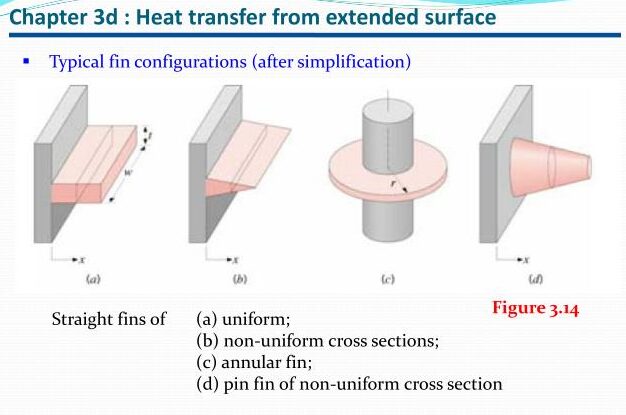
Figure 7: Types of Extended Surfaces
8. Unsteady State Conduction
Unsteady state conduction, or transient heat conduction, occurs when the temperature within a material changes with time. This is common in situations where heat sources are applied or removed.
8.1 Lumped System Analysis
The lumped system analysis assumes that the temperature within the object is uniform at any given time. It simplifies the analysis by considering the object as a single thermal mass.
Where:
- θ(t) = Temperature at time t
- θ∞ = Ambient temperature
- θ0 = Initial temperature
- Rth = Thermal resistance
- Cth = Thermal capacitance
This model is useful for understanding how quickly an object responds to changes in thermal conditions.
8.2 Biot and Fourier Numbers
Biot number (Bi) and Fourier number (Fo) are dimensionless numbers used to analyze transient heat conduction problems.
Where:
- Bi = Biot number
- h = Heat transfer coefficient
- L = Characteristic length
- k = Thermal conductivity
- Fo = Fourier number
- α = Thermal diffusivity
- t = Time
Biot number helps determine whether the lumped system assumption is valid, while Fourier number is used to characterize the rate of heat conduction within the material.
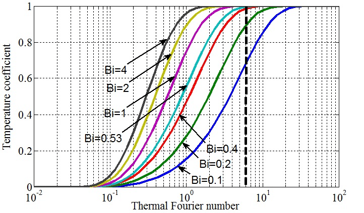
Figure 8: Biot and Fourier Numbers in Heat Conduction
8.3 Heisler Chart
The Heisler chart provides solutions for transient heat conduction problems, particularly in situations with varying boundary conditions. It is used to find temperature distributions in solid objects over time.
Example calculations can be performed using the Heisler chart to determine temperature profiles in practical applications.
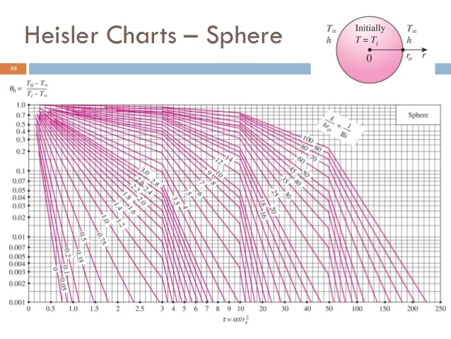
Figure 9: Heisler Chart for Transient Heat Conduction
Unit 3: Principles of Convection
1. Continuity, Momentum, and Energy Equations
In fluid dynamics, the continuity, momentum, and energy equations describe the behavior of fluids and heat transfer within them. These equations are fundamental for analyzing convective heat transfer.
1.1 Continuity Equation
The continuity equation ensures mass conservation in a fluid flow:
Where:
- ρ = Fluid density
- v = Velocity vector
- ∇ = Del operator
This equation states that the rate of change of density within a control volume plus the divergence of the mass flux must equal zero.
1.2 Momentum Equation
The momentum equation, or Navier-Stokes equation, describes the motion of fluid particles:
Where:
- p = Pressure
- μ = Dynamic viscosity
- g = Gravitational acceleration
This equation accounts for pressure forces, viscous forces, and external forces such as gravity.
1.3 Energy Equation
The energy equation describes the conservation of energy in the fluid:
Where:
- Cp = Specific heat capacity at constant pressure
- k = Thermal conductivity
- T = Temperature
- Q = Heat source term
This equation considers the rate of change of thermal energy within a control volume, heat conduction, and internal heat generation.
2. Boundary Layers
Boundary layers are regions near a solid boundary where fluid velocity and temperature gradients are significant.
2.1 Hydro-dynamic Boundary Layer
The hydro-dynamic boundary layer is the layer of fluid where the velocity changes from zero at the surface to the free stream velocity:
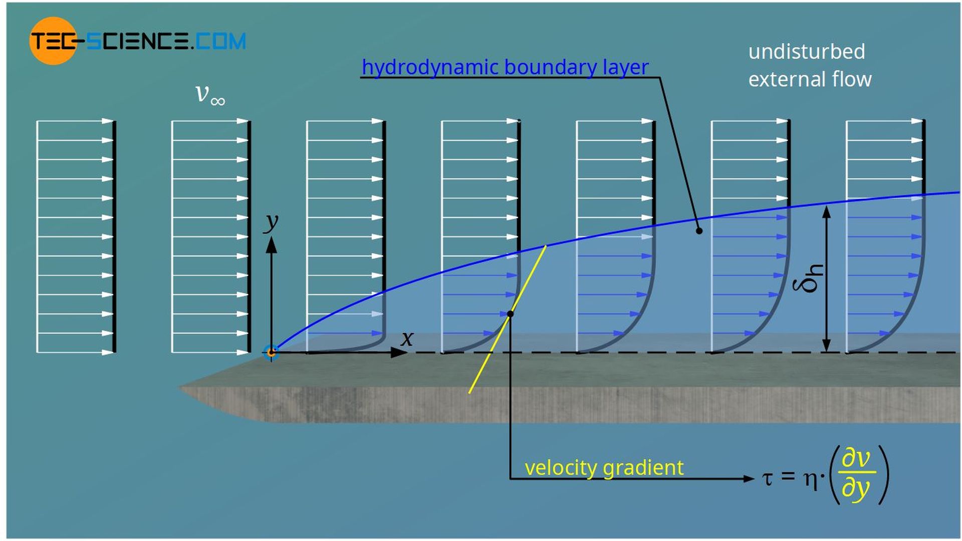
Figure 1: Hydro-dynamic Boundary Layer on a Flat Plate
2.2 Thermal Boundary Layer
The thermal boundary layer describes the region where temperature changes from the surface temperature to the free stream temperature:
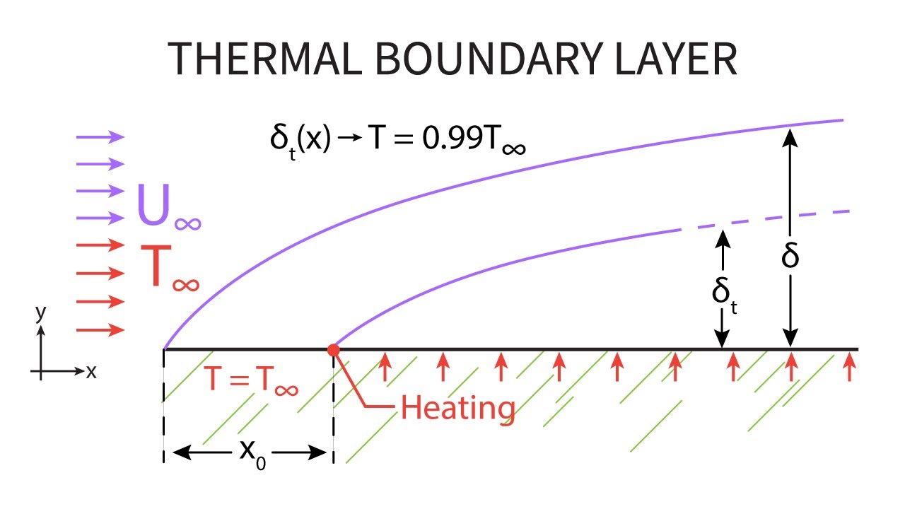
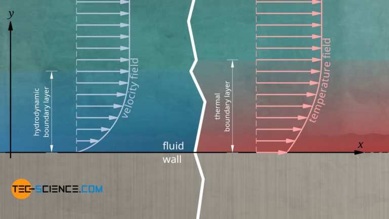
Figure 2: Thermal Boundary Layer on a Flat Plate
3. Dimensionless Groups in Forced Convection
Dimensionless groups help in analyzing and comparing convective heat transfer characteristics across different systems.
3.1 Reynolds Number (Re)
The Reynolds number measures the ratio of inertial forces to viscous forces:
Where:
- ρ = Fluid density
- v = Flow velocity
- L = Characteristic length
- μ = Dynamic viscosity
A high Reynolds number indicates turbulent flow, while a low Reynolds number indicates laminar flow.
3.2 Nusselt Number (Nu)
The Nusselt number represents the ratio of convective to conductive heat transfer:
Where:
- h = Convective heat transfer coefficient
- L = Characteristic length
- k = Thermal conductivity
A higher Nusselt number indicates more effective convection.
3.3 Prandtl Number (Pr)
The Prandtl number relates momentum diffusivity to thermal diffusivity:
Where:
- ν = Kinematic viscosity
- α = Thermal diffusivity
It helps determine the relative thickness of the momentum and thermal boundary layers.
4. Forced Convection
Forced convection involves fluid flow driven by external means such as fans or pumps.
4.1 Empirical Relations for Pipe and Tube Flow
Empirical relations are used to estimate heat transfer coefficients in different flow conditions:
Where:
- C, m, n = Empirical constants depending on flow conditions
- Re = Reynolds number
- Pr = Prandtl number
Common correlations include the Dittus-Boelter equation for turbulent flow in pipes.
4.2 Flow Across Cylinders, Spheres, and Tube Banks
Heat transfer in these geometries is analyzed using empirical correlations specific to each shape:
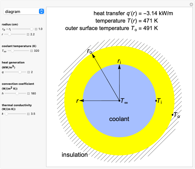
Figure 3: Flow Across Cylinders and Spheres
Each shape has different characteristics for heat transfer and requires different empirical relations.
5. Free Convection
Free convection occurs due to buoyancy forces arising from temperature differences within the fluid.
5.1 Free Convection from Vertical, Inclined, and Horizontal Surfaces
The heat transfer rate from these surfaces can be estimated using empirical relations:
Where:
- Gr = Grashof number
- Pr = Prandtl number
Different surface orientations affect the convective heat transfer characteristics.
5.2 Free Convection from Cylinders and Spheres
For cylinders and spheres, the heat transfer is analyzed based on the shape’s effect on natural convection:
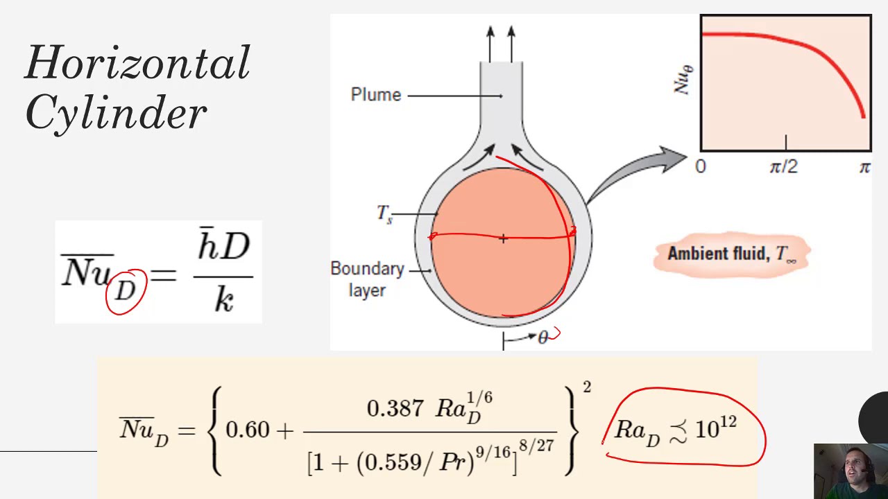
Figure 4: Free Convection from Cylinders and Spheres
Unit 4: Heat Exchangers
1. Classification of Heat Exchangers
Heat exchangers are devices used to transfer heat between two or more fluids. They can be classified based on different criteria:
1.1 Based on Flow Arrangement
- Counterflow: Fluids flow in opposite directions. This configuration allows for higher thermal efficiency.
- Parallel Flow: Fluids flow in the same direction. It is simpler but less efficient compared to counterflow.
- Crossflow: Fluids flow perpendicular to each other. Common in air-cooled heat exchangers.
- Shell and Tube: One fluid flows through the tubes and another around the tubes within the shell.
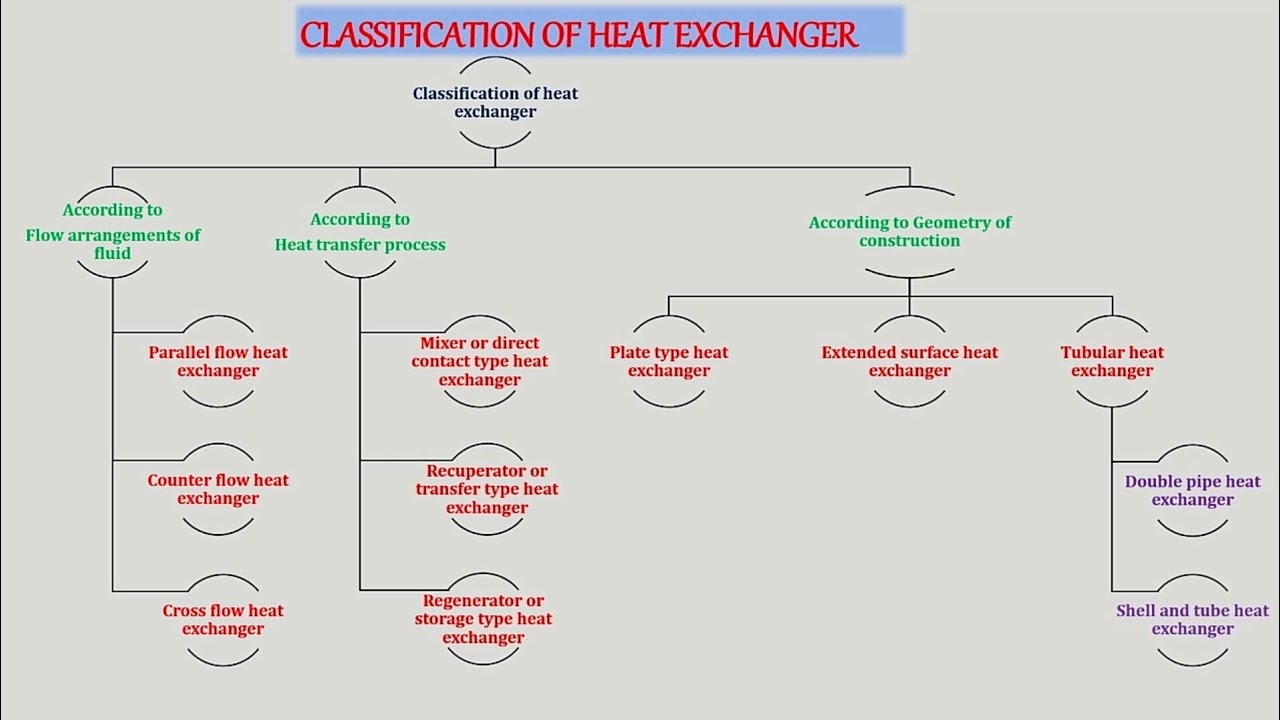
Figure 1: Classification of Heat Exchangers
2. Temperature Distribution
Temperature distribution in heat exchangers varies based on the flow arrangement:
2.1 Parallel Flow Arrangement
In a parallel flow heat exchanger, both hot and cold fluids enter the exchanger at the same end and move in the same direction. The temperature difference between the two fluids decreases along the length of the heat exchanger:
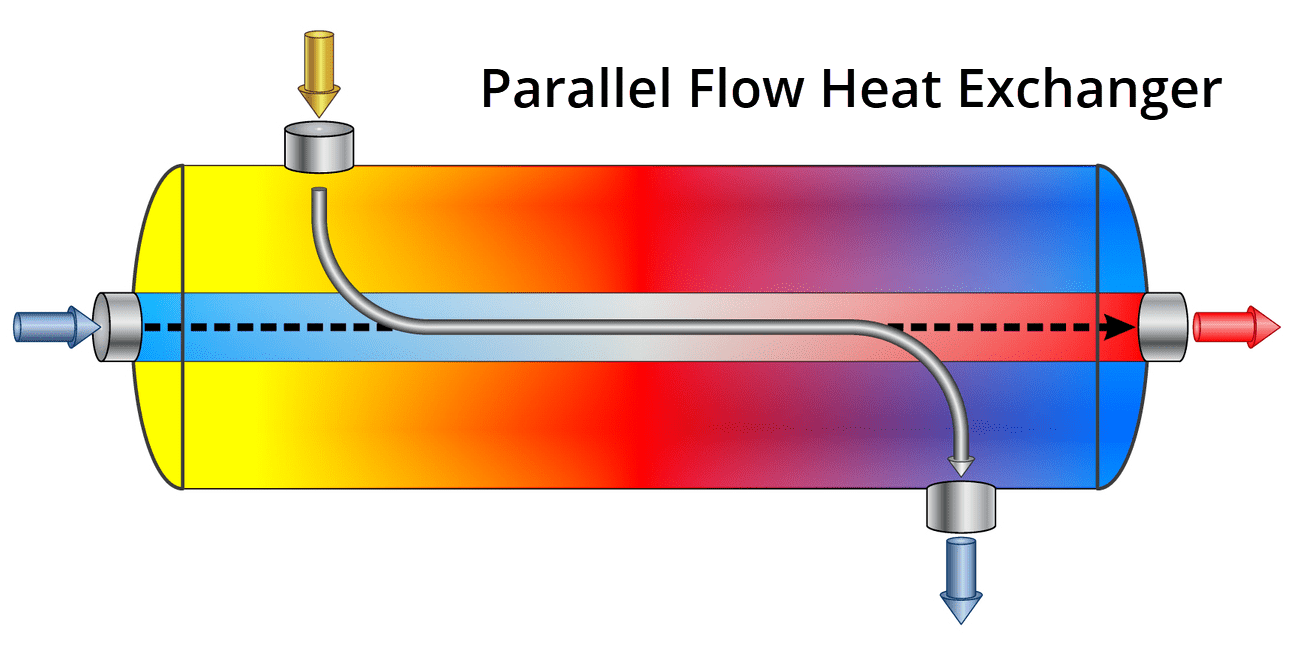
Figure 2: Parallel Flow Heat Exchanger
2.2 Counterflow Arrangement
In a counterflow heat exchanger, the fluids flow in opposite directions. This arrangement maximizes the temperature difference between the fluids and achieves higher thermal efficiency:
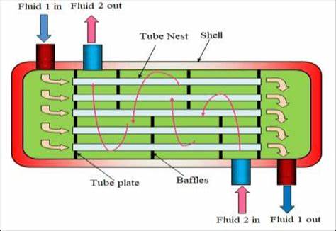
Figure 3: Counterflow Heat Exchanger
3. Overall Heat Transfer Coefficient
The overall heat transfer coefficient (U) represents the heat transfer rate per unit area and per unit temperature difference between the fluids:
Where:
- Q = Heat transfer rate (W)
- A = Heat exchanger area (m²)
- ΔT = Temperature difference (K)
- U = Overall heat transfer coefficient (W/m²·K)
The overall heat transfer coefficient is influenced by factors such as fluid properties, flow arrangement, and surface conditions.
4. Analysis of Heat Exchangers
Heat exchanger performance can be analyzed using various methods:
4.1 Log Mean Temperature Difference (LMTD) Method
The LMTD method calculates the average temperature difference between the hot and cold fluids across the length of the heat exchanger:
Where:
- ΔT1 = Temperature difference at one end
- ΔT2 = Temperature difference at the other end
- ΔTlm = Log mean temperature difference
4.2 Effectiveness – NTU Method
The effectiveness–NTU method determines the heat exchanger’s performance based on the number of transfer units (NTU) and the capacity rate ratio:
Where:
- ε = Effectiveness
- Q = Actual heat transfer rate (W)
- Qmax = Maximum possible heat transfer rate (W)
NTU can be determined using empirical correlations or heat exchanger performance charts.
5. Selection of Heat Exchangers
The selection of a heat exchanger depends on various factors including:
- Heat Duty: The amount of heat to be transferred.
- Fluid Properties: Viscosity, density, and thermal conductivity of the fluids.
- Space Constraints: Available space for installation.
- Cost: Initial and operating costs.
6. Introduction to TEMA Standard
The Tubular Exchanger Manufacturers Association (TEMA) standard provides guidelines for the design, fabrication, and testing of shell and tube heat exchangers:
- Types of Exchangers: TEMA classifies heat exchangers into various types such as A, B, and C based on their construction.
- Design Criteria: Includes design pressures, temperatures, and material specifications.
- Testing: Ensures the heat exchangers meet performance and safety standards.
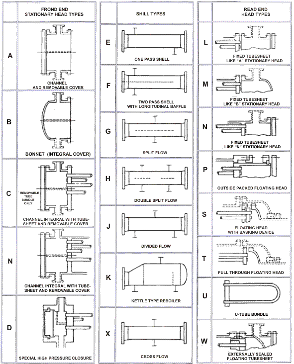
Figure 4: TEMA Standard Classification
Unit 5: Radiation Heat Transfer
1. Introduction
Radiation heat transfer is the process of energy transfer in the form of electromagnetic waves, primarily in the infrared spectrum. Unlike conduction and convection, which require a medium, radiation can occur through a vacuum.
2. Thermal Radiation
Thermal radiation is emitted by all bodies with a temperature above absolute zero. The amount and spectrum of emitted radiation depend on the body’s temperature and material properties.
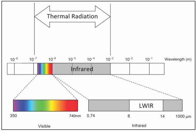
Figure 1: Spectrum of Thermal Radiation
3. Black Body Radiation
A black body is an idealized physical body that absorbs all incident radiation and re-emits it perfectly. The radiation emitted by a black body is characterized by Planck’s law:
Where:
- Eb(λ, T) = Spectral emissive power (W/m²·m)
- λ = Wavelength (m)
- T = Absolute temperature (K)
- h = Planck’s constant (J·s)
- c = Speed of light in a vacuum (m/s)
- k = Boltzmann constant (J/K)
4. Radiation Laws
4.1 Stefan-Boltzmann Law
The total emissive power of a black body is proportional to the fourth power of its absolute temperature:
Where:
- Eb = Total emissive power (W/m²)
- σ = Stefan-Boltzmann constant (5.67 × 10⁻⁸ W/m²·K4)
- T = Absolute temperature (K)
4.2 Wien’s Displacement Law
Wien’s Law relates the wavelength at which the emission of a black body spectrum is maximized to the temperature:
Where:
- λmax = Wavelength of peak emission (m)
- b = Wien’s displacement constant (2.897 × 10⁻³ m·K)
- T = Absolute temperature (K)
5. Radiation Properties
Different surfaces have different radiation properties, which include:
- Emissivity (ε): The ratio of radiation emitted by a surface to that emitted by a black body at the same temperature.
- Reflectivity (ρ): The ratio of reflected radiation to incident radiation.
- Absorptivity (α): The ratio of absorbed radiation to incident radiation.
For any surface, the sum of absorptivity, reflectivity, and transmissivity is 1:
6. Atmospheric and Solar Radiation
6.1 Atmospheric Radiation
The Earth’s atmosphere absorbs and re-emits radiation. It affects the temperature and radiation exchange between the Earth’s surface and space.
6.2 Solar Radiation
Solar radiation is the energy emitted by the Sun, primarily in the visible and ultraviolet spectra. It varies with the time of day, season, and geographic location:
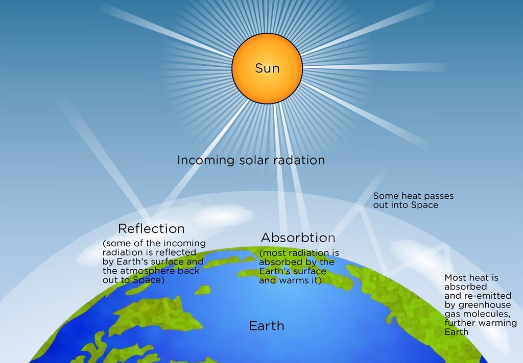 Figure 2: Solar Radiation and its Effects
7. The View Factor
The view factor (or configuration factor) is the fraction of radiation leaving a surface that directly reaches another surface. It is used in radiation heat transfer calculations and depends on the geometry of the surfaces:
Where:
- Fij = View factor from surface i to surface j
- Ai = Area of surface i
- Aj = Area of surface j
- θi = Angle between surface i and the line of sight
- θj = Angle between surface j and the line of sight
- r = Distance between surfaces i and j
8. Radiation Heat Transfer from Different Surfaces
8.1 Black Surfaces
Black surfaces absorb all incident radiation and emit the maximum possible radiation for their temperature:
8.2 Gray Surfaces
Gray surfaces have a constant emissivity less than 1. The radiation heat transfer for gray surfaces is given by:
Where ε is the emissivity of the gray surface.
8.3 Diffuse Surfaces
Diffuse surfaces emit radiation uniformly in all directions. The heat transfer is calculated using the emissivity of the surface:
8.4 Radiation Shields
Radiation shields are used to reduce heat transfer between surfaces by reflecting radiation. Their effectiveness depends on their reflectivity and placement:
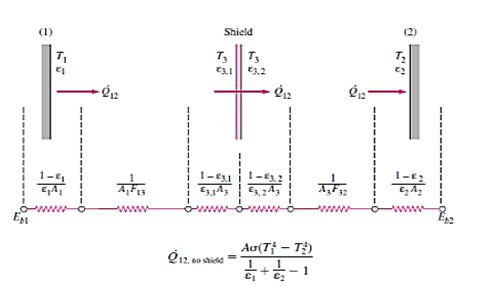 Figure 3: Radiation Shield and Its Effect
Texts:
- F. P. Incorpera, D. P. Dewitt, “Fundamentals of Heat and Mass Transfer”, John Wiley, 5th edition, 1990.
- S. P. Sukhatme, “A Textbook On Heat Transfer”, Tata McGraw-Hill Publications, 3rd edition.
References:
- Y. A. Cengel, “Heat Transfer – A Practical Approach”, Tata McGraw Hill Publications, 3rd edition, 2006.
- J. P. Holman, “Heat Transfer”, Tata McGraw Hill Publications, 9th edition, 2004.
