Theory of Machines 02
Unit 1: Belt Drives
1. Flat Belts
A flat belt is a simple mechanical device used to transfer power between two shafts via friction. It consists of a flat loop of material that runs over pulleys. Let’s explore the essential concepts:
Effect of Slip
Slip occurs when the belt cannot grip the pulleys tightly enough, causing a difference in speed between the driver and driven pulleys. Slip reduces power transmission efficiency. It is usually caused by low tension or improper alignment of the belt on the pulleys.
Creep
Creep refers to the gradual elongation and shortening of the belt as it moves over pulleys. This happens because the belt stretches on the side with higher tension and contracts on the side with lower tension. This small but consistent movement can cause power losses.
Crowning of Pulley
Pulleys are often designed with a slight convex shape, known as “crowning,” to ensure that the belt stays centered on the pulley. Crowning helps prevent the belt from drifting off the pulley, especially in high-speed applications.
Length of Belt
The length of a flat belt is calculated based on the distance between the centers of the two pulleys and their diameters. The formula to calculate the length of an open belt drive is:
Where:
- L = Length of the belt
- C = Distance between the centers of the pulleys
- D = Diameter of the larger pulley
- d = Diameter of the smaller pulley
Centrifugal Tension
When the belt moves at high speed, a centrifugal force acts outward due to the belt’s inertia. This force increases the overall tension in the belt, reducing the available tension for transmitting power.
Initial Tension in Belts
Initial tension refers to the tension that is set in the belt when the system is stationary. This initial tension ensures that the belt grips the pulley tightly enough to avoid slip. Proper initial tension is crucial for efficient power transmission.
Ratio of Belt Tensions
The tension ratio between the tight and slack sides of the belt can be calculated using the following formula:
Where:
- T1 = Tension on the tight side
- T2 = Tension on the slack side
- μ = Coefficient of friction
- θ = Angle of contact (in radians)
Power Transmitted
The power transmitted by the belt can be calculated using the following formula:
Where:
- P = Power transmitted
- v = Velocity of the belt
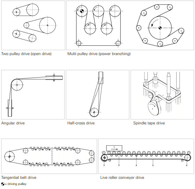
Figure 1: Flat Belt Drive System
2. V-Belts
V-belts are more efficient and reliable for transmitting power compared to flat belts. They have a V-shaped cross-section, which allows them to grip the pulleys more effectively.
Advantages of V-Belts over Flat Belts
V-belts offer several advantages over flat belts:
- Increased friction and better grip, reducing the chances of slip.
- Compact design, making them suitable for applications with limited space.
- Higher load-carrying capacity due to the wedge action between the belt and pulley.
- More efficient power transmission due to better contact with the pulley grooves.
Ratio of Belt Tensions
For V-belts, the tension ratio is modified by the wedge angle of the belt. The formula is:
Where:
- α = Half angle of the V-belt groove
- Other terms are the same as for flat belts.
Torque Transmitted
The torque transmitted by a V-belt drive is given by the equation:
Where:
- T = Torque transmitted
- R = Radius of the pulley
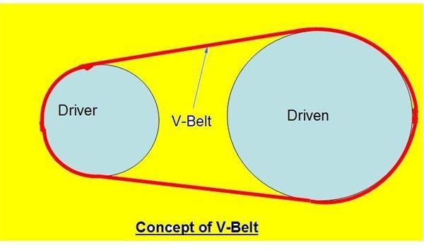
Figure 2: V-Belt Drive System
Both flat and V-belt drives have their specific applications. Flat belts are simpler but prone to slip and creep, whereas V-belts provide better grip, power transmission, and reduced vibration. Understanding the principles behind belt drives helps in selecting the right drive for mechanical systems.
Unit 2: Toothed Gears
1. Classification of Gears
Gears are mechanical devices used to transfer motion and power between shafts. They are classified based on their shape, orientation of shafts, and tooth geometry. The major types of gears include:
- Spur Gears: These gears have straight teeth and are used for parallel shafts.
- Helical Gears: These gears have angled teeth, which engage more gradually, allowing for smoother operation.
- Bevel Gears: These are used for intersecting shafts and have conically shaped teeth.
- Worm Gears: A type of gear consisting of a worm (screw-like gear) meshing with a worm wheel.
- Internal Gears: Gears where the teeth are cut on the inside surface of a cylinder.
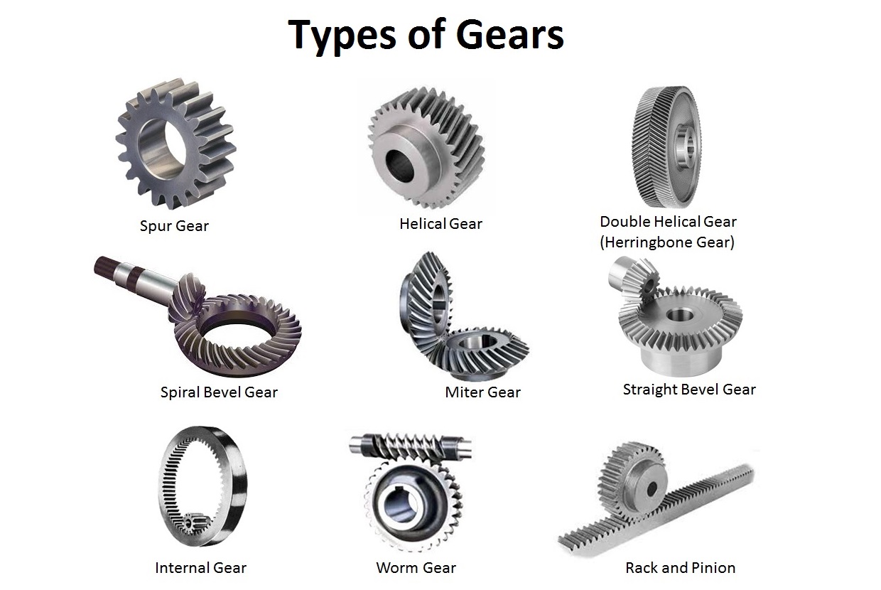
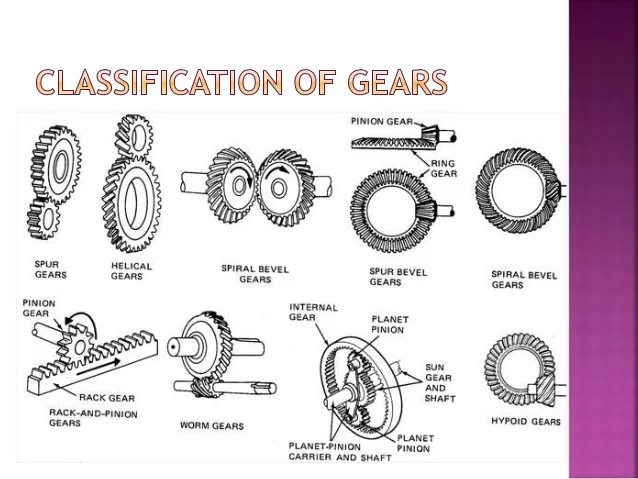
Figure 1: Classification of Gears
2. Terminology of Spur Gears
Spur gears are the most common type of gears. To understand their functioning, we need to know certain key terms:
- Pitch Circle Diameter (PCD): The diameter of the circle on which the teeth are arranged. It determines the size of the gear.
- Module: The ratio of the pitch circle diameter to the number of teeth. It is denoted by m and is measured in mm:m = PCD / Z
Where Z is the number of teeth.
- Addendum: The radial distance from the pitch circle to the top of the tooth.
- Dedendum: The radial distance from the pitch circle to the bottom of the tooth space.
- Pressure Angle (α): The angle between the line of action and the tangent to the pitch circle.
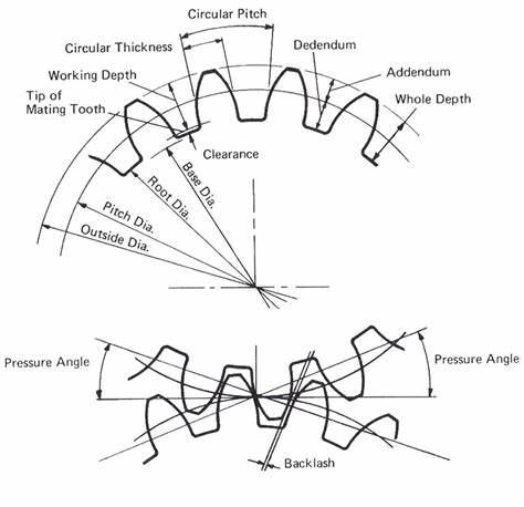
Figure 2: Spur Gear Terminology
3. Conjugate Action
Conjugate action ensures smooth transmission of motion between two gears. In conjugate action, the velocity ratio of the gears remains constant throughout the engagement of teeth. This is crucial for smooth and efficient power transmission.
Involute and Cycloidal Profiles
There are two main types of gear tooth profiles:
- Involute Profile: The most commonly used profile in modern gears. It ensures constant velocity ratio and provides smooth meshing.
- Cycloidal Profile: Used in some specialized applications. This profile has better strength and wear resistance but is more complex to manufacture.
Path of Contact
The path of contact is the locus of the points of contact between two meshing gears. For involute gears, the path of contact is a straight line.
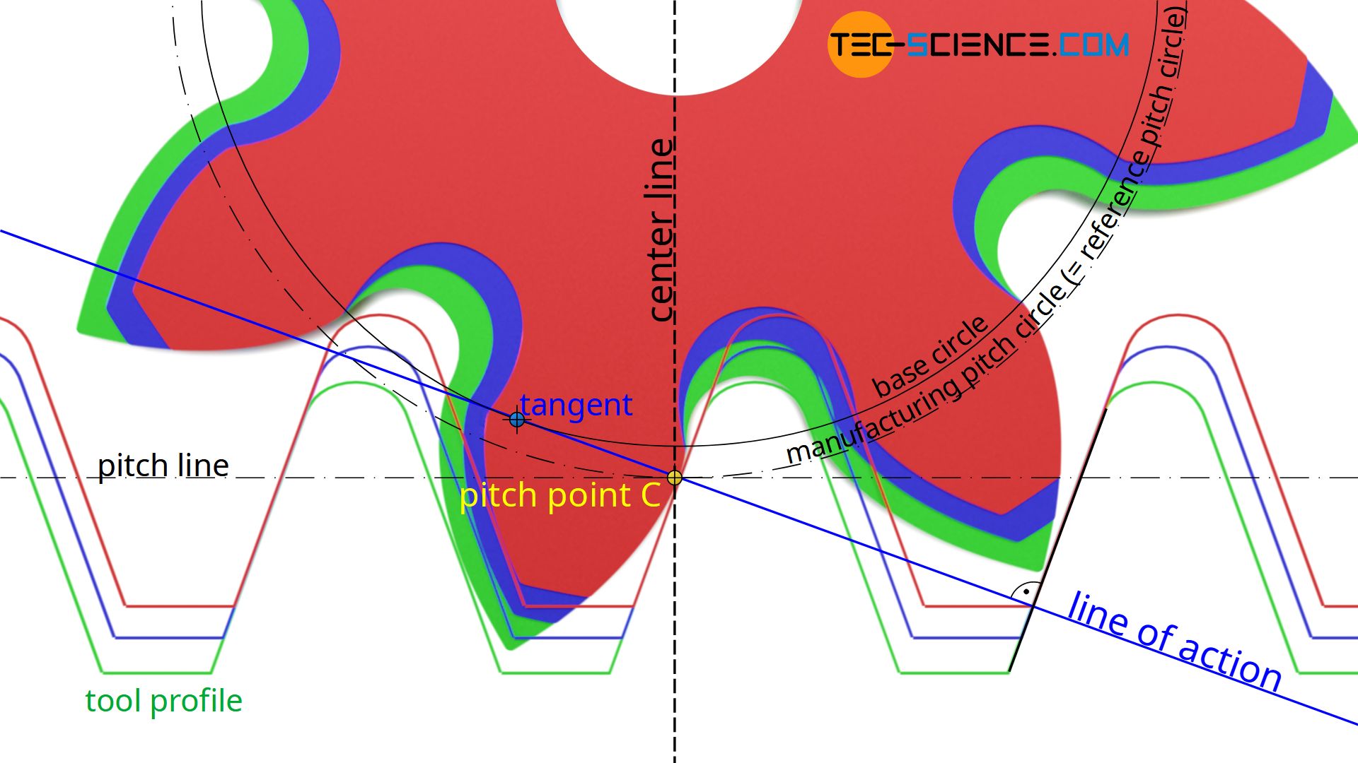
Figure 3: Involute Gear Profile
Arc of Contact
The arc of contact is the length of the path over which two gear teeth remain in contact during meshing. It is divided into the following:
- Arc of Approach: The part of the path where the tooth comes into contact.
- Arc of Recession: The part of the path where the tooth leaves contact.
Contact Ratio
The contact ratio defines the average number of teeth in contact at any given time. A higher contact ratio ensures smoother operation. The formula to calculate contact ratio is:
4. Interference and Undercutting
Interference: Occurs when the non-working part of the tooth comes into contact with the other gear. This can lead to excessive wear and failure.
Undercutting: To prevent interference, teeth may be cut in a way that reduces their base. This process is called undercutting, but it reduces tooth strength.
5. Backlash
Backlash refers to the clearance or gap between two meshing gear teeth. It is important to have a slight amount of backlash to allow for thermal expansion and to ensure smooth operation. Excessive backlash, however, can lead to inaccuracies in motion transmission.
6. Introduction to Internal Gears
Internal gears have teeth on the inside surface of a cylinder. They are often used in planetary gear systems where space is limited. These gears engage with external gears and are used in compact mechanisms like gear pumps and some types of transmissions.
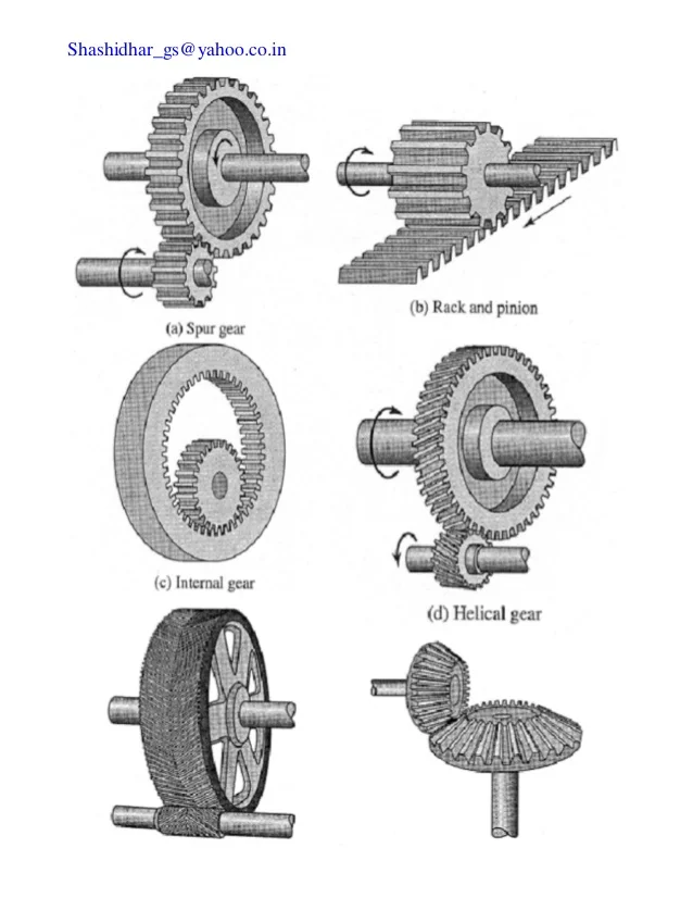
Figure 4: Internal Gear
7. Helical Gear Terminology
Helical gears have teeth that are cut at an angle to the axis of rotation. This allows the teeth to engage gradually, providing smoother operation than spur gears. Important terminology for helical gears includes:
- Normal Module: The module measured perpendicular to the helix angle.
- Transverse Module: The module measured along the axis of the gear.
- Helix Angle: The angle between the tooth trace and the axis of the gear.
Virtual Number of Teeth
The virtual number of teeth in a helical gear is the equivalent number of teeth it would have if it were a spur gear. This is used in calculations to compare helical gears to spur gears.
Where:
- Zv = Virtual number of teeth
- Z = Actual number of teeth
- β = Helix angle
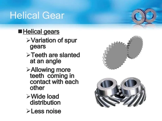
Figure 5: Helical Gear
Toothed gears are essential components in mechanical systems that transfer motion and power between shafts. Understanding the terminology, profiles, and special features like interference and backlash is crucial for designing efficient gear systems. Helical and spur gears have their unique advantages, with helical gears offering smoother operation and spur gears providing simplicity in design.
Unit 3: Worm & Bevel Gears and Gear Trains
1. Introduction to Worm Gears
Worm gears are a type of gear arrangement in which a worm (screw-like gear) meshes with a worm wheel. This system is used when a large reduction in speed and a corresponding increase in torque are required. Worm gears are typically used in applications like conveyor systems, lifting mechanisms, and automotive steering systems.
Key Terminology for Worm Gears
- Worm: A gear in the shape of a screw that meshes with the teeth of the worm wheel. It typically has a very high lead angle.
- Worm Wheel: The gear that meshes with the worm. It usually has teeth on the outer circumference.
- Lead Angle: The angle between the helical thread of the worm and the plane perpendicular to its axis. The lead angle is crucial for determining the motion transfer in a worm gear system.
- Helix Angle: The angle between the worm’s teeth and its axis of rotation. It is similar to the lead angle but applies to multiple-start threads.
- Self-locking: A property of some worm gear systems where the motion cannot be reversed, meaning that the worm wheel cannot drive the worm.
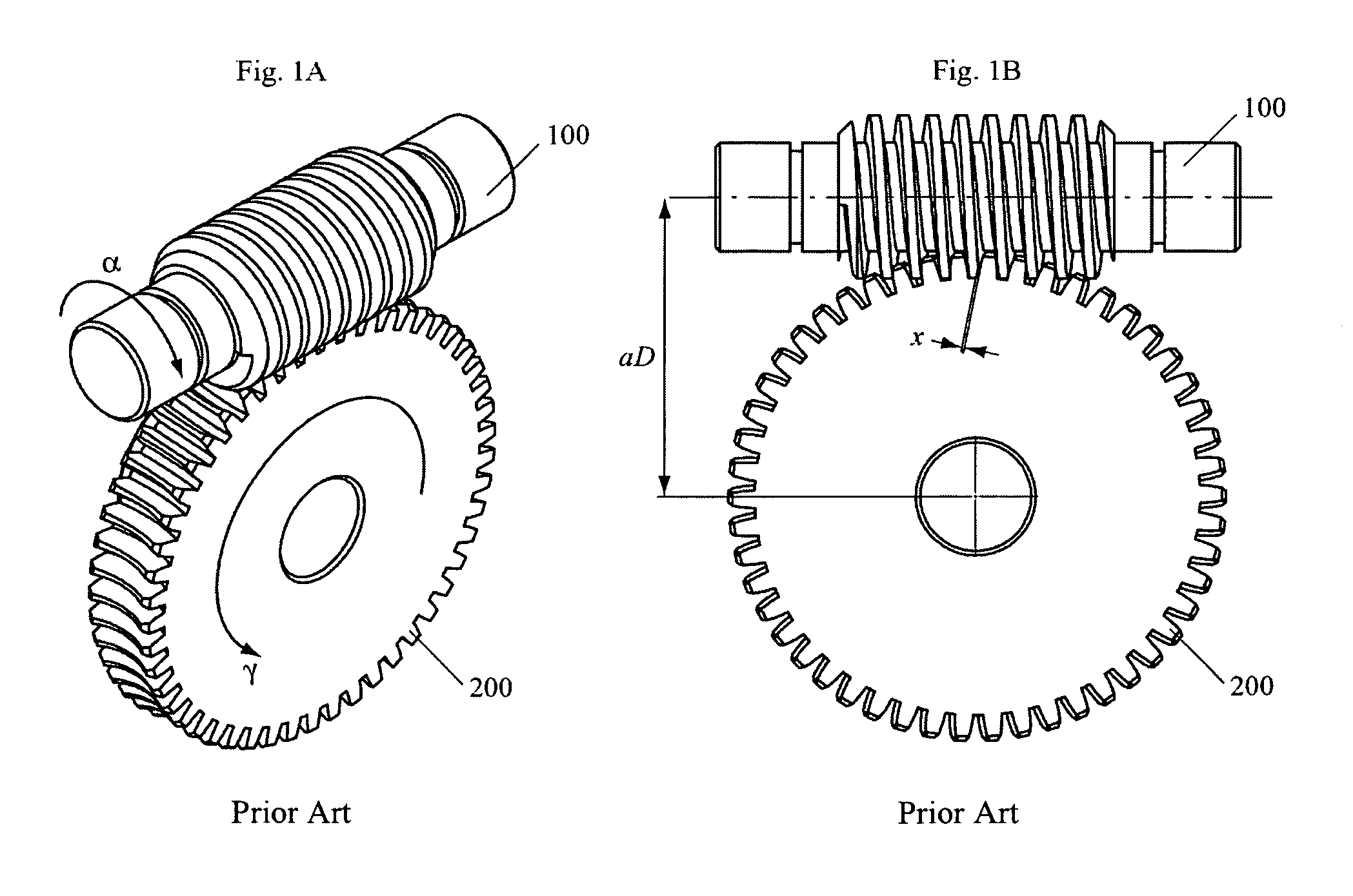
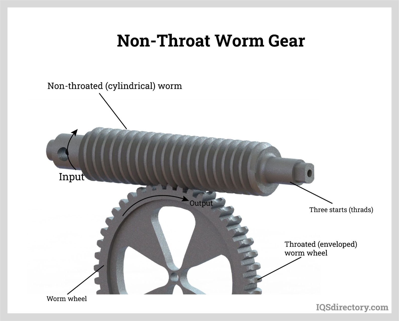
Figure 1: Worm Gear System
Efficiency of Worm Gear
The efficiency of worm gear systems is relatively low due to the sliding contact between the worm and the worm wheel teeth, which causes significant friction. The efficiency of a worm gear is calculated using the formula:
Where:
- λ = Lead angle of the worm
- μ = Coefficient of friction between the worm and worm wheel
The higher the lead angle, the higher the efficiency of the worm gear. However, high lead angles also decrease the self-locking property of the system.
2. Introduction to Bevel Gears
Bevel gears are conical gears that are used to transmit motion between intersecting shafts, typically at a 90-degree angle. They are commonly used in differential drives, hand drills, and heavy machinery.
Key Terminology for Bevel Gears
- Pitch Angle: The angle formed between the face of the bevel gear and its axis. The pitch angles of two meshing bevel gears must add up to 90 degrees.
- Cone Distance: The distance between the apex of the cone-shaped pitch surface and the center of the gear face.
- Face Width: The width of the bevel gear tooth measured along the face of the gear.
- Back Cone Angle: The angle between the pitch cone and a line parallel to the axis of the gear.
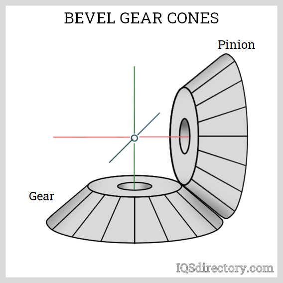
Figure 2: Bevel Gear System
Concept of Virtual Number of Teeth in Bevel Gear
In bevel gears, the virtual number of teeth refers to the equivalent number of teeth that would be present in a spur gear of the same size. The formula for calculating the virtual number of teeth in bevel gears is:
Where:
- Zv = Virtual number of teeth
- Z = Actual number of teeth
- β = Pitch angle of the bevel gear
This concept is important because it allows us to treat bevel gears as equivalent spur gears for the purpose of calculations.
3. Gear Trains
A gear train is a combination of two or more gears working together to transmit motion. Gear trains are used to increase or decrease the speed or torque of a system. There are various types of gear trains, each suited for specific applications.
Types of Gear Trains
Simple Gear Train
In a simple gear train, gears are arranged such that each gear is mounted on its own shaft. The velocity ratio in a simple gear train is determined by the ratio of the number of teeth on the driving gear to the number of teeth on the driven gear. The formula for the velocity ratio is:
Where:
- Nd = Number of teeth on the driven gear
- Nf = Number of teeth on the driving gear
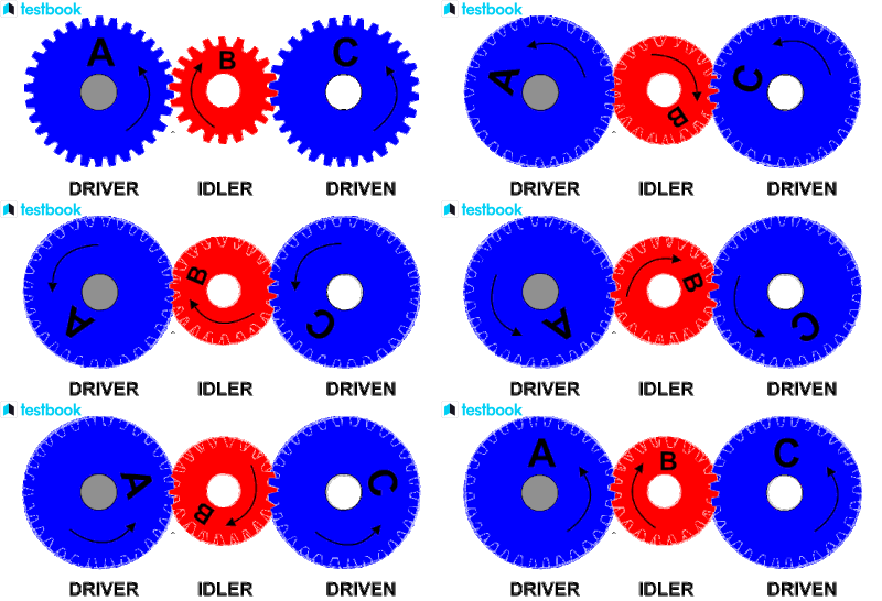
Figure 3: Simple Gear Train
Compound Gear Train
A compound gear train is used when there is a need for a large reduction in speed or a large increase in torque. In a compound gear train, multiple gears are mounted on the same shaft, which allows for a more complex transmission of motion. The velocity ratio is the product of the velocity ratios of each pair of gears.
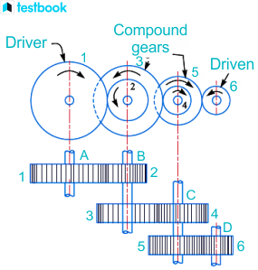
Figure 4: Compound Gear Train
Reverted Gear Train
In a reverted gear train, the input and output shafts are on the same axis. This arrangement is often used in clock mechanisms and machine tools. The velocity ratio is similar to that of a compound gear train.
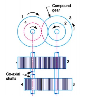
Figure 5: Reverted Gear Train
Epicyclic Gear Train
An epicyclic gear train, also known as a planetary gear train, consists of one or more gears (planet gears) rotating around a central gear (sun gear). This type of gear train is commonly used in automatic transmissions and differential mechanisms.
Velocity Ratios in Epicyclic Gear Trains
In an epicyclic gear train, the velocity ratio depends on the number of teeth in the sun gear, the planet gear, and the ring gear. The formula for calculating the velocity ratio is:
Where:
- Zr = Number of teeth on the ring gear
- Zs = Number of teeth on the sun gear
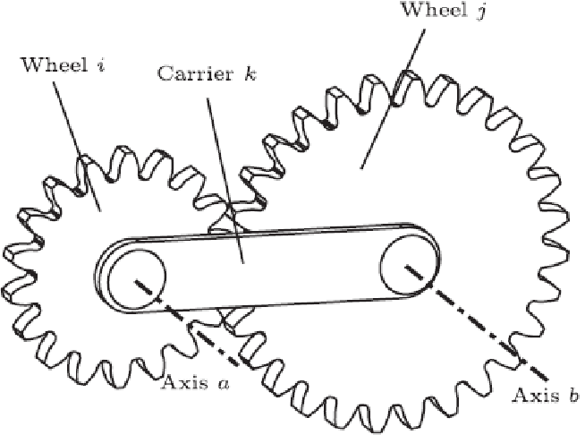
Figure 6: Epicyclic Gear Train
Epicyclic gear trains offer high torque in a compact form and are commonly used in power transmission systems where space is limited.
Unit 4: Flywheel and Gyroscope
1. Flywheel
A flywheel is a mechanical device that stores rotational energy. It is commonly used in engines and machinery to smooth out fluctuations in speed and energy delivery. Flywheels are crucial for maintaining consistent power output in applications such as internal combustion engines and punching presses.
Turning Moment Diagram
The turning moment diagram represents the variation of the turning moment (torque) over a complete cycle of the engine. This diagram helps in visualizing the energy fluctuations throughout the operation cycle.
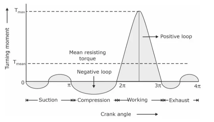
Figure 1: Turning Moment Diagram
Energy Stored in the Flywheel
The energy (E) stored in a flywheel is given by the formula:
Where:
- E = Energy stored in the flywheel (Joules)
- I = Moment of inertia of the flywheel (kg·m²)
- ω = Angular velocity (rad/s)
Fluctuation of Energy and Speed
The fluctuation of energy in a flywheel is the difference between the maximum and minimum energy levels during operation. This fluctuation is crucial for ensuring a stable output speed, particularly in applications where the load varies.
Determination of Mass of Flywheel
To determine the mass of a flywheel for a four-stroke single-cylinder internal combustion engine, we use the following relationship:
Where:
- M = Mass of the flywheel (kg)
- T = Torque (N·m)
- g = Acceleration due to gravity (9.81 m/s²)
- h = Height of the flywheel’s center of mass above the axis of rotation (m)
For a simple punching press, the mass of the flywheel can also be determined using similar principles, factoring in the energy required to perform the punching operation.
2. Gyroscope
A gyroscope is a device that uses the principles of angular momentum to maintain orientation. Gyroscopes are used in various applications, including navigation systems, aerospace, and robotics.
Principles of Gyroscopic Action
The principle of gyroscopic action states that when a spinning object experiences an external torque, it will respond by changing its orientation. This response is perpendicular to the direction of the applied torque, a phenomenon known as precession.
Precession and Gyroscopic Acceleration
Precession is the phenomenon where the axis of a spinning gyroscope moves in response to an applied force. The gyroscopic acceleration (ag) can be expressed as:
Where:
- τ = Torque applied (N·m)
- I = Moment of inertia of the gyroscope (kg·m²)
Gyroscopic Couple
The gyroscopic couple (Cg) is the torque resulting from the gyroscopic effect when a gyroscope is subjected to an external torque. It can be calculated using the formula:
Where:
- ω = Angular velocity of the gyroscope (rad/s)
- ag = Gyroscopic acceleration (rad/s²)
Effects of the Gyroscopic Couple
The gyroscopic couple has various effects in different applications:
- Aeroplanes: In aviation, gyroscopic stability helps maintain orientation during flight, particularly during maneuvers.
- Naval Ships: Gyroscopes are used in stabilizing systems to reduce rolling motion in rough seas.
- Four Wheelers: In vehicles, gyroscopic effects contribute to stability during turns and help maintain balance during sudden maneuvers.
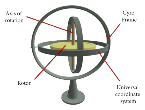
Figure 2: Gyroscope Action
Unit 5: Vibration
1. Mechanical Vibration
Mechanical vibration refers to the oscillation of an object around its equilibrium position. Understanding vibrations is crucial in mechanical design to prevent failures and ensure safety in machinery and structures.
Basic Concepts and Definitions
- Vibration: A mechanical oscillation about an equilibrium position.
- Frequency: The number of oscillations per unit time, typically measured in Hertz (Hz).
- Amplitude: The maximum displacement from the equilibrium position.
- Natural Frequency: The frequency at which a system tends to oscillate in the absence of any driving force.
Single Degree of Freedom System
A single degree of freedom (SDOF) system can be described by a single coordinate that defines its position. Common examples include a mass attached to a spring or a simple pendulum.
Undamped Free Vibrations
In undamped free vibrations, the system oscillates indefinitely without any energy loss. The equation of motion for an SDOF system can be expressed as:
Where:
- m = Mass of the system (kg)
- k = Spring constant (N/m)
- x(t) = Displacement from equilibrium (m)
Natural Frequency of Vibrations
The natural frequency (fn) of longitudinal and transverse vibrations of a shaft with point loads can be calculated using:
Where:
- k = Equivalent stiffness of the system (N/m)
- m = Mass of the vibrating body (kg)
Introduction to Damped Free Vibrations
In real-world applications, vibrations are often damped due to energy loss mechanisms such as friction or air resistance. The equation of motion for damped vibrations is given by:
Where:
- c = Damping coefficient (Ns/m)
- x'(t) = Velocity of displacement (m/s)
Types of Damping
- Undamped: No energy loss, perpetual oscillation.
- Viscous Damping: Damping proportional to velocity.
- Coulomb Damping: Damping due to friction.
- Structural Damping: Energy dissipation in materials.
Critical or Whirling Speed of Shaft in Undamped System
The critical speed (ωc) is the speed at which resonance occurs, leading to large amplitude vibrations. It is given by:
Where:
- g = Gravitational acceleration (9.81 m/s²)
- r = Radius of the shaft (m)
Introduction to Forced Vibrations
Forced vibrations occur when a periodic force is applied to a system. The system will oscillate at the frequency of the applied force, potentially leading to resonance if the forcing frequency approaches the system’s natural frequency.
2. Torsional Vibrations
Torsional vibrations involve rotational oscillations around the axis of a shaft or rotor. Understanding these vibrations is essential for designing rotating machinery.
Natural Frequency and Modes of Torsional Vibration
The natural frequency of a torsional system can be calculated using:
Where:
- G = Shear modulus of the material (Pa)
- J = Polar moment of inertia (m4)
- I = Mass moment of inertia (kg·m2)
Modes of torsional vibration describe how different parts of a system oscillate relative to each other. Higher modes correspond to higher frequencies and more complex oscillatory patterns.
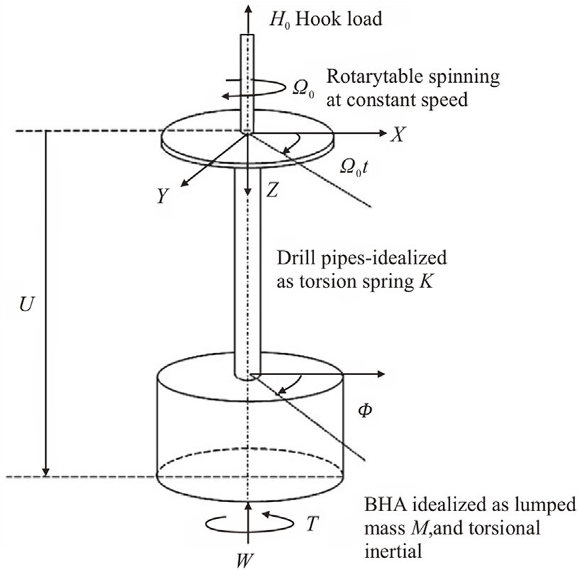
Figure 1: Torsional Vibration Modes
Texts:
- S. S. Rattan, “Theory of Machines,” Tata McGraw Hill Publications, New Delhi.
- Thomas Beven, “Theory of Machines,” CBS Publishers, Delhi, 1984.
- Kelly, Graham S., “Mechanical Vibrations,” Schaum’s Outline Series, McGraw Hill, New York, 1996.
- Rao, J.S., “Introductory Course on Theory and Practice of Mechanical Vibration,” New Age International (P) Ltd, New Delhi, 2nd edition, 1999.
References:
- Rao Singiresu, “Mechanical Vibrations,” Pearson Education, New Delhi, 4th edition 2004.
- J. E. Shigley, J. J. Vicker, “Theory of Machines and Mechanisms,” Tata McGraw Hill International.

Thank you so much for this notes, it helped us a lot