Unit 1: Drawing Standards and Geometrical Construction
1. Drawing Standards (SP: 46)
Drawing standards are essential for ensuring uniformity and clarity in technical drawings. SP: 46 is a standard set by the Bureau of Indian Standards (BIS) that outlines various conventions for technical drawing. This standard covers:
- Type of Lines: Different lines represent different features in technical drawings, such as:
- Continuous Line: Used for outlines and edges.
- Dashed Line: Indicates hidden details.
- Dotted Line: Used for center lines and symmetry.
- Chain Line: Indicates a line of reference.
- Lettering: Proper lettering standards ensure clarity. Recommended height and style for text include:
- Capital letters for titles and important labels.
- Lowercase letters for dimensions and annotations.
- Dimensioning: Clear dimensioning is vital for accurate interpretation. It involves:
- Using arrowheads and dimension lines.
- Placement of dimensions outside the drawing where possible.
- Scaling Conventions: Drawings may be made to scale to fit on paper. Common scales include 1:1, 1:2, and 1:10.
2. Geometrical Construction
Geometrical construction techniques are fundamental skills in engineering drawing. These methods allow for the accurate representation of shapes and figures. Below are key constructions with descriptions.
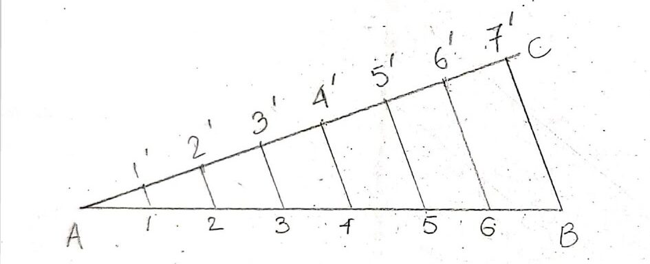
2.1 Dividing a Given Straight Line into Equal Parts
To divide a line segment into equal parts, follow these steps:
- Draw a line segment AB.
- Draw a ray AC at an angle (e.g., 30 degrees) from point A.
- Using a compass, mark off equal lengths on ray AC (e.g., points D, E, etc.).
- Connect the last point on ray AC to point B.
- Draw parallel lines from points D, E, etc., to line AB. The intersections will divide AB into equal parts.
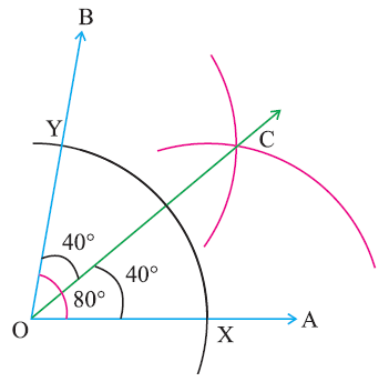
2.2 Bisecting a Given Angle
To bisect an angle, follow these steps:
- Draw angle ∠ABC.
- Using a compass, draw arcs from points A and B to intersect at point D.
- With the same radius, draw arcs from points D to intersect at point E.
- Draw a line from C through E. This line bisects the angle ∠ABC.
2.3 Drawing a Regular Polygon Given One Side
To draw a regular polygon (e.g., pentagon, hexagon) with a known side length:
- Start with a line segment representing one side.
- Using a compass, set the radius equal to the side length.
- Draw arcs to create vertices around the initial side, ensuring that each side is equal.
- Connect the vertices to form the polygon.
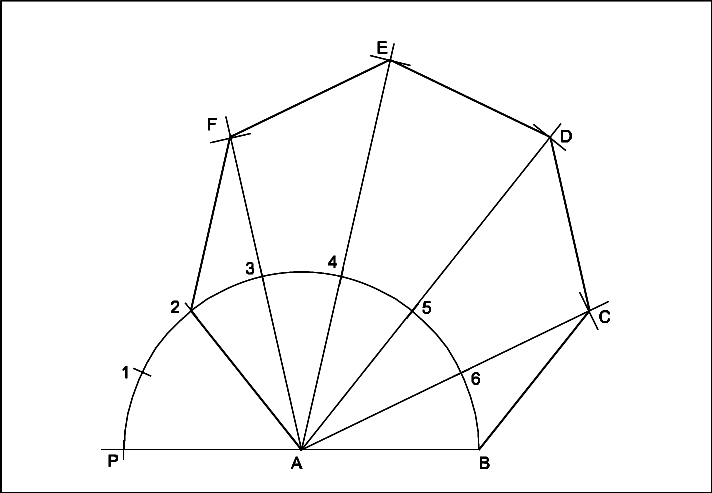
2.4 Special Methods of Constructing a Pentagon and a Hexagon
Specific constructions can simplify drawing regular pentagons and hexagons:
Pentagon Construction:
- Draw a circle with a radius equal to the desired side length.
- Mark the center and construct a diameter.
- Use compass and straightedge to find intersections that represent the vertices of the pentagon.
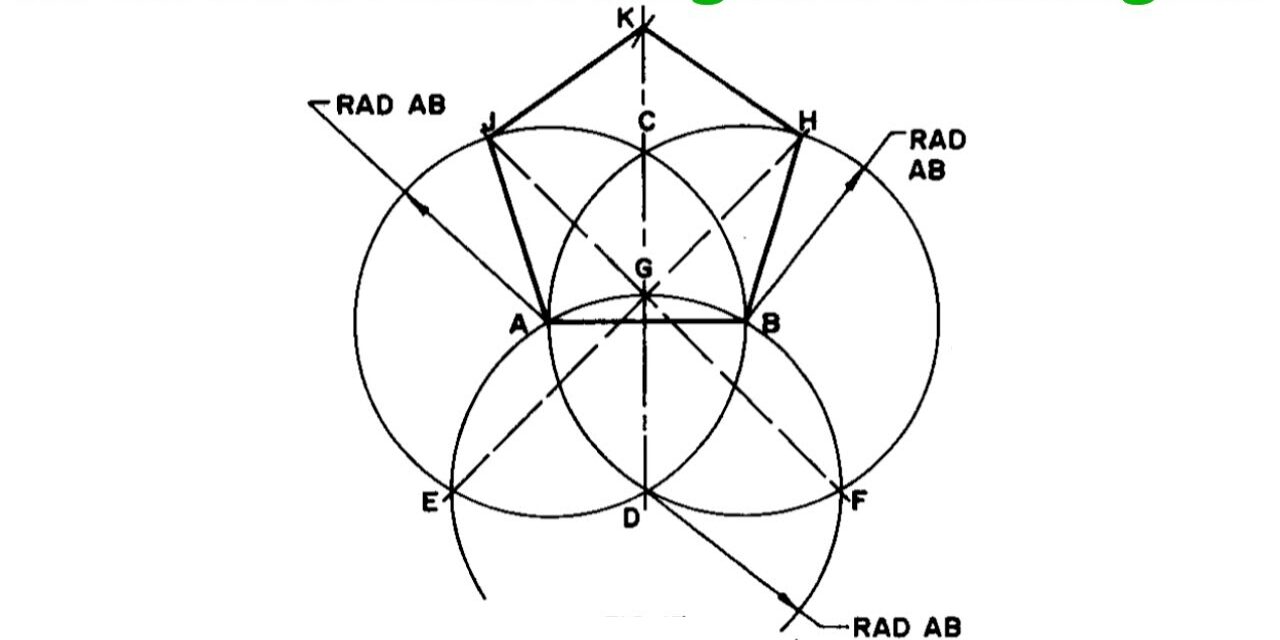
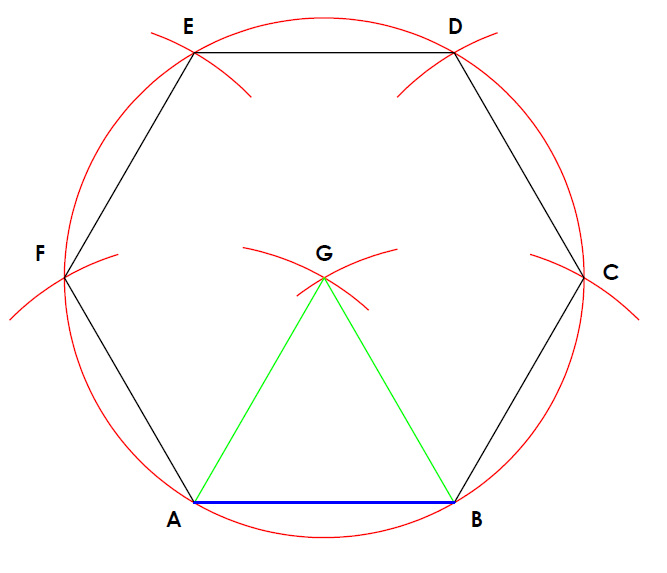
Hexagon Construction:
- Draw a circle with the radius equal to the desired side length.
- Mark the center and divide the circle into six equal segments using the compass.
- Connect these points to form the hexagon.
Mastering drawing standards and geometrical construction techniques is crucial for anyone engaged in engineering drawing and design. These skills not only ensure clarity and precision in technical communication but also form the foundation for more complex design tasks.
Unit 2: Orthographic Projections and Projections of Points
1. Introduction to Orthographic Projection
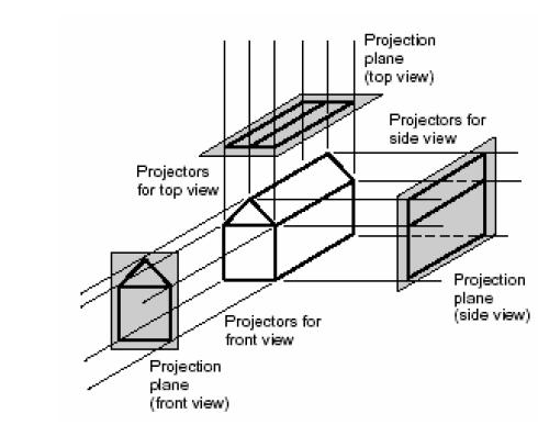
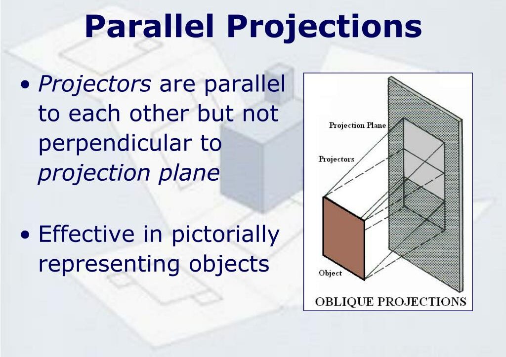
Orthographic projection is a method of representing three-dimensional objects in two dimensions. This technique involves projecting the object’s features onto a plane using parallel lines perpendicular to the plane. The primary goal is to convey accurate dimensions and shapes without distortion.
In orthographic projection, multiple views of an object are provided, typically including:
- Front View: Displays the height and width.
- Top View: Displays the width and depth.
- Side View: Displays the height and depth.
These views collectively provide a comprehensive representation of the object, allowing for precise interpretation and construction.
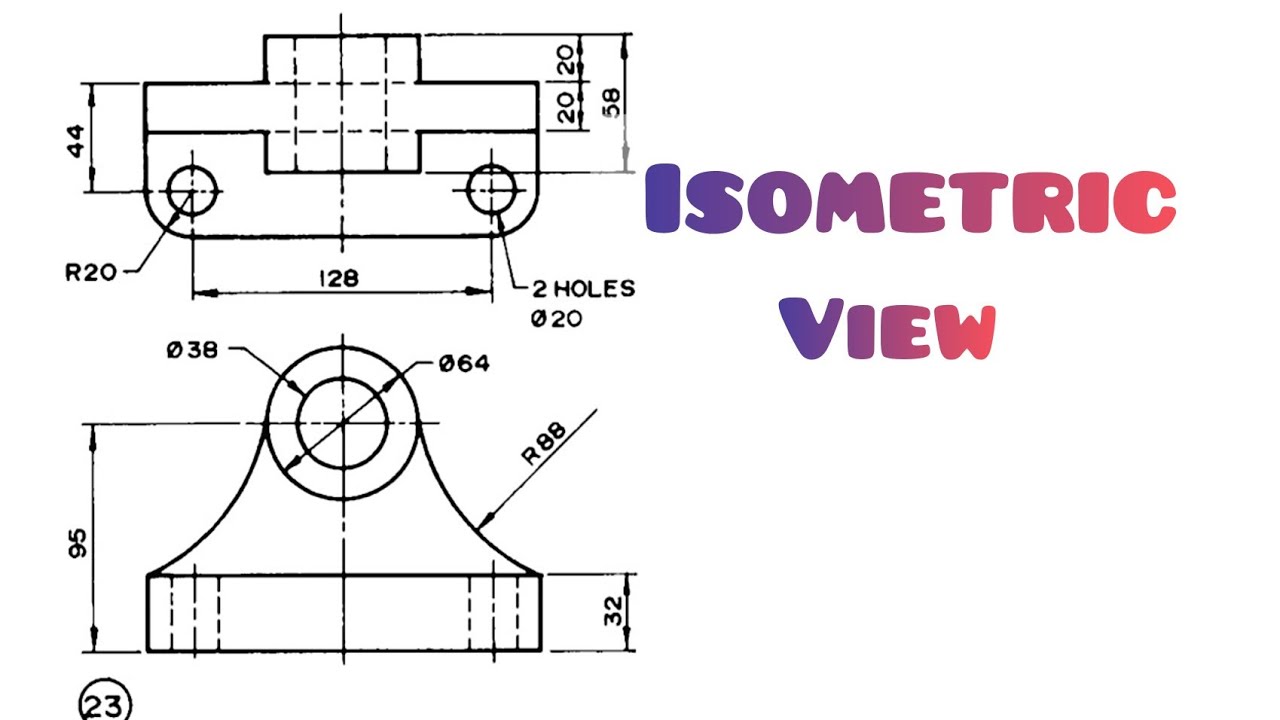
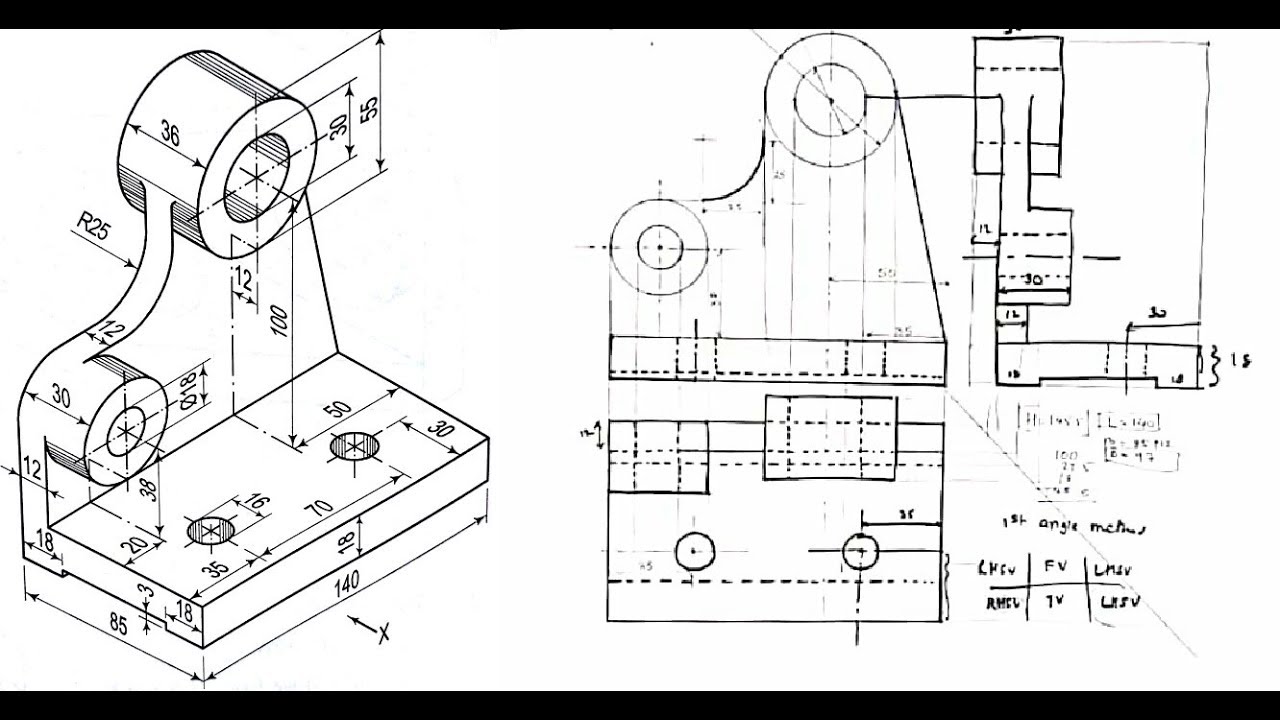
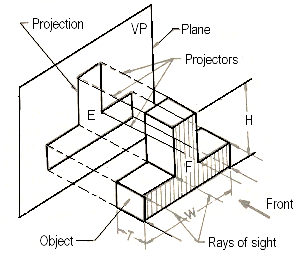
2. Drawing Orthographic Views from Isometric Views
Converting an isometric view to orthographic views involves identifying the dimensions and angles presented in the isometric drawing. The following steps can guide this process:
- Identify the dimensions of the object in the isometric view.
- Choose a suitable scale for the orthographic views.
- Project the necessary lines vertically and horizontally from the isometric view to construct the front, top, and side views.
- Ensure all views are aligned properly to maintain true proportions.
An example of converting an isometric view to orthographic views is shown below:
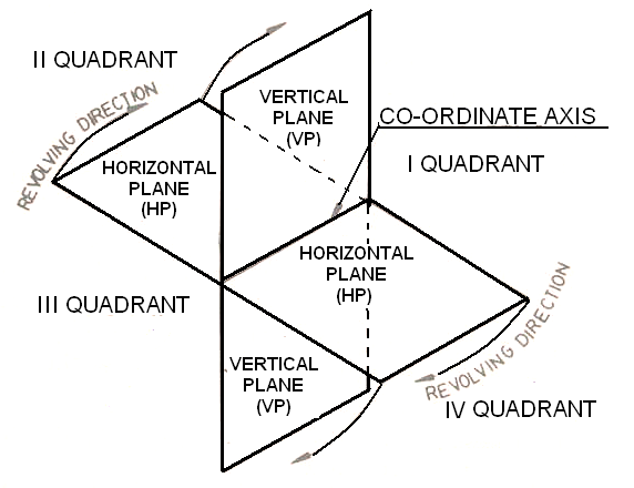
3. Projection of Points Lying in Four Quadrants
Points can exist in four quadrants when projected in a three-dimensional space. The quadrants are defined based on the signs of the coordinates (x, y, z). The classification of quadrants is as follows:
- First Quadrant: (x, y) are both positive; z can be positive or negative.
- Second Quadrant: (x is negative, y is positive); z can be positive or negative.
- Third Quadrant: (x, y) are both negative; z can be positive or negative.
- Fourth Quadrant: (x is positive, y is negative); z can be positive or negative.
To project a point onto the respective quadrants, follow these steps:
- Identify the coordinates of the point.
- Determine which quadrant the point lies in based on its x, y, and z values.
- Project the point onto the respective projection planes (horizontal and vertical) for that quadrant.
- Mark the projected point in the appropriate orthographic view.
Here’s a visual representation of points in the four quadrants:
Understanding orthographic projections and the projections of points in various quadrants is crucial for effective technical drawing. Mastering these concepts allows for precise representation and interpretation of three-dimensional objects in two dimensions, which is foundational in fields such as engineering and architecture.
Unit 3: Projections of Straight Lines and Planes and Their Traces
1. Projections of Straight Lines
The projection of a straight line onto a plane shows how the line appears when viewed from that plane. Depending on the orientation of the line with respect to the projection planes (horizontal and vertical), the projections can vary. We will explore various cases:
1.1 Lines Parallel to One or Both Planes
A line can be parallel to one plane (either horizontal or vertical) or both planes. When a line is parallel to a plane, its projection on that plane will be a straight line of the same length. For example:
The diagram above shows a line parallel to the HP, where the projection on the HP is the full length of the line, and the projection on the VP is a point.
1.2 Lines Perpendicular to One or Both Planes
If a line is perpendicular to one of the planes, its projection on that plane will be a point, and its projection on the other plane will be the full length of the line.
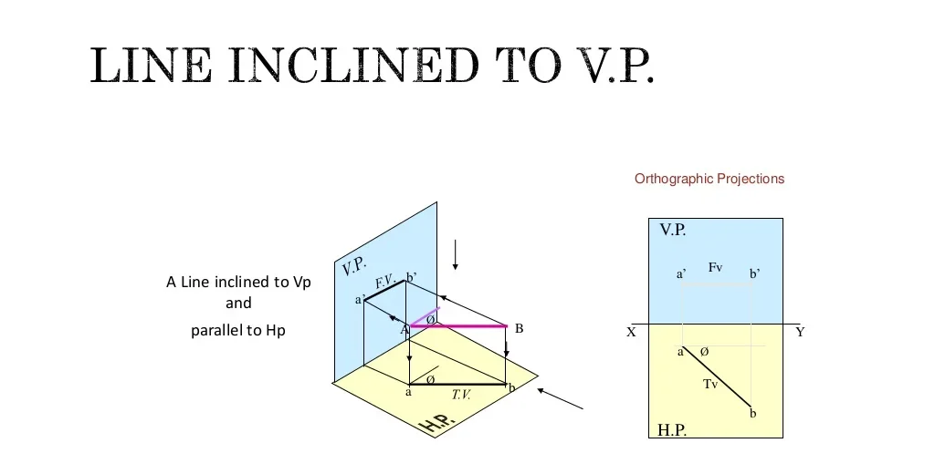
1.3 Lines Inclined to One or Both Planes
When a line is inclined to one plane, its projection on that plane is a line, but shorter than the true length of the line. The projection on the other plane will represent the inclination.
Projected Length (L) = True Length (T) * cos(θ)
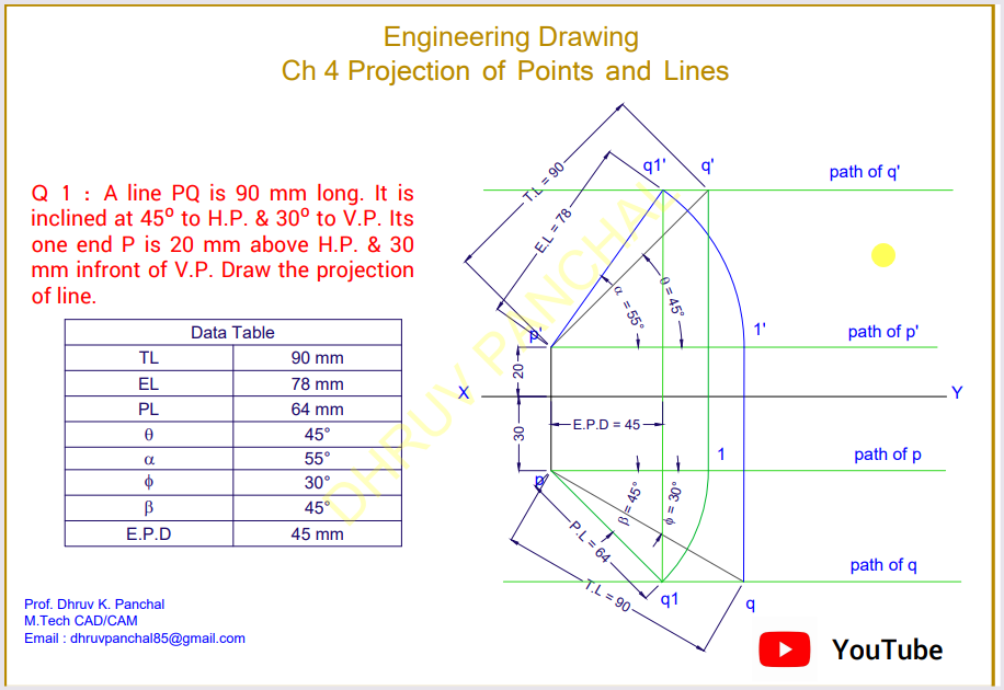
The diagram above shows a line inclined to the HP. The projection on the HP is shorter than the true length, while the projection on the VP reflects the angle of inclination.
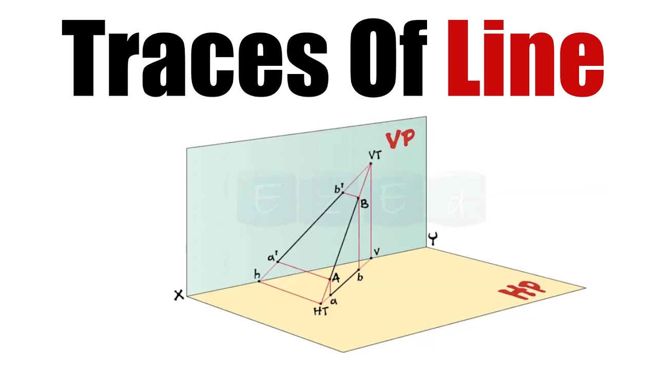
2. Traces of Lines
Traces of a line are the points where the line intersects the projection planes (HP or VP). These points are known as the horizontal trace (HT) and vertical trace (VT) of the line.
- Horizontal Trace (HT): The point where the line intersects the horizontal plane.
- Vertical Trace (VT): The point where the line intersects the vertical plane.
3. Projections of Planes
A plane can be projected onto the horizontal plane (HP) and vertical plane (VP) similar to lines, depending on its orientation. We will examine cases where planes are parallel, perpendicular, or inclined to one or both planes.
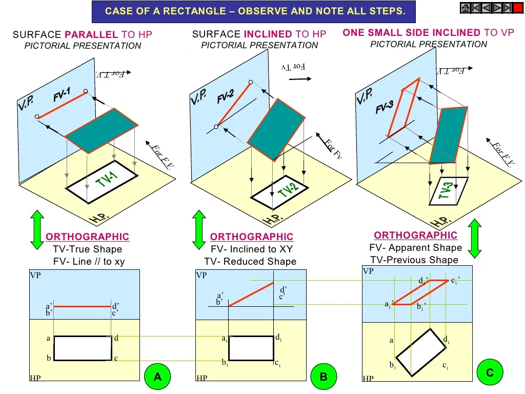
3.1 Planes Parallel to One or Both Planes
When a plane is parallel to the HP or VP, its projection on that plane will appear as the true shape of the plane. The projection on the other plane will be a line or an edge.
3.2 Planes Perpendicular to One or Both Planes
If a plane is perpendicular to one of the projection planes, its projection on that plane will be a line representing its edge, and the projection on the other plane will be the true shape of the plane.
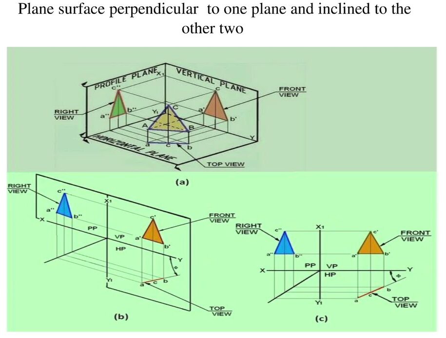
3.3 Planes Inclined to One or Both Planes
When a plane is inclined to one of the planes, its projection will appear as a distorted shape, and the degree of distortion will depend on the angle of inclination.
4. Traces of Planes
The traces of a plane are the lines where the plane intersects the projection planes. The horizontal trace (HT) is the line where the plane meets the HP, and the vertical trace (VT) is the line where it meets the VP.
- Horizontal Trace (HT): The intersection of the plane with the horizontal plane (HP).
- Vertical Trace (VT): The intersection of the plane with the vertical plane (VP).
Understanding the projections of lines and planes is essential for accurate technical drawings and engineering designs. This knowledge allows us to visualize and represent three-dimensional objects on two-dimensional planes, providing valuable insight into their structure and orientation.
Unit 3: Projections of Straight Lines and Planes and Their Traces
1. Projections of Straight Lines
The projection of a straight line onto a plane shows how the line appears when viewed from that plane. Depending on the orientation of the line with respect to the projection planes (horizontal and vertical), the projections can vary. We will explore various cases:
1.1 Lines Parallel to One or Both Planes
A line can be parallel to one plane (either horizontal or vertical) or both planes. When a line is parallel to a plane, its projection on that plane will be a straight line of the same length. For example:
The diagram above shows a line parallel to the HP, where the projection on the HP is the full length of the line, and the projection on the VP is a point.
1.2 Lines Perpendicular to One or Both Planes
If a line is perpendicular to one of the planes, its projection on that plane will be a point, and its projection on the other plane will be the full length of the line.
1.3 Lines Inclined to One or Both Planes
When a line is inclined to one plane, its projection on that plane is a line, but shorter than the true length of the line. The projection on the other plane will represent the inclination.
Projected Length (L) = True Length (T) * cos(θ)
The diagram above shows a line inclined to the HP. The projection on the HP is shorter than the true length, while the projection on the VP reflects the angle of inclination.
2. Traces of Lines
Traces of a line are the points where the line intersects the projection planes (HP or VP). These points are known as the horizontal trace (HT) and vertical trace (VT) of the line.
- Horizontal Trace (HT): The point where the line intersects the horizontal plane.
- Vertical Trace (VT): The point where the line intersects the vertical plane.
3. Projections of Planes
A plane can be projected onto the horizontal plane (HP) and vertical plane (VP) similar to lines, depending on its orientation. We will examine cases where planes are parallel, perpendicular, or inclined to one or both planes.
3.1 Planes Parallel to One or Both Planes
When a plane is parallel to the HP or VP, its projection on that plane will appear as the true shape of the plane. The projection on the other plane will be a line or an edge.
3.2 Planes Perpendicular to One or Both Planes
If a plane is perpendicular to one of the projection planes, its projection on that plane will be a line representing its edge, and the projection on the other plane will be the true shape of the plane.
3.3 Planes Inclined to One or Both Planes
When a plane is inclined to one of the planes, its projection will appear as a distorted shape, and the degree of distortion will depend on the angle of inclination.
4. Traces of Planes
The traces of a plane are the lines where the plane intersects the projection planes. The horizontal trace (HT) is the line where the plane meets the HP, and the vertical trace (VT) is the line where it meets the VP.
- Horizontal Trace (HT): The intersection of the plane with the horizontal plane (HP).
- Vertical Trace (VT): The intersection of the plane with the vertical plane (VP).
Understanding the projections of lines and planes is essential for accurate technical drawings and engineering designs. This knowledge allows us to visualize and represent three-dimensional objects on two-dimensional planes, providing valuable insight into their structure and orientation.
Unit 5: Sectioning of Solids and Isometric Projections
1. Sectioning of Solids
Sectioning is a technique used in engineering graphics to represent the internal features of solids. By cutting through a solid at a specific plane, we can visualize its internal structure.
1.1 Section Planes
Section planes can be oriented in different ways, including:
- Perpendicular to One Plane: A section plane perpendicular to the horizontal plane (HP) will reveal the internal features in the vertical projection.
- Parallel to One Plane: A section plane parallel to the vertical plane (VP) shows the true shape of the section in the horizontal projection.
- Inclined to One Plane: If the section plane is inclined, the resulting projection can show a distorted view of the internal features.
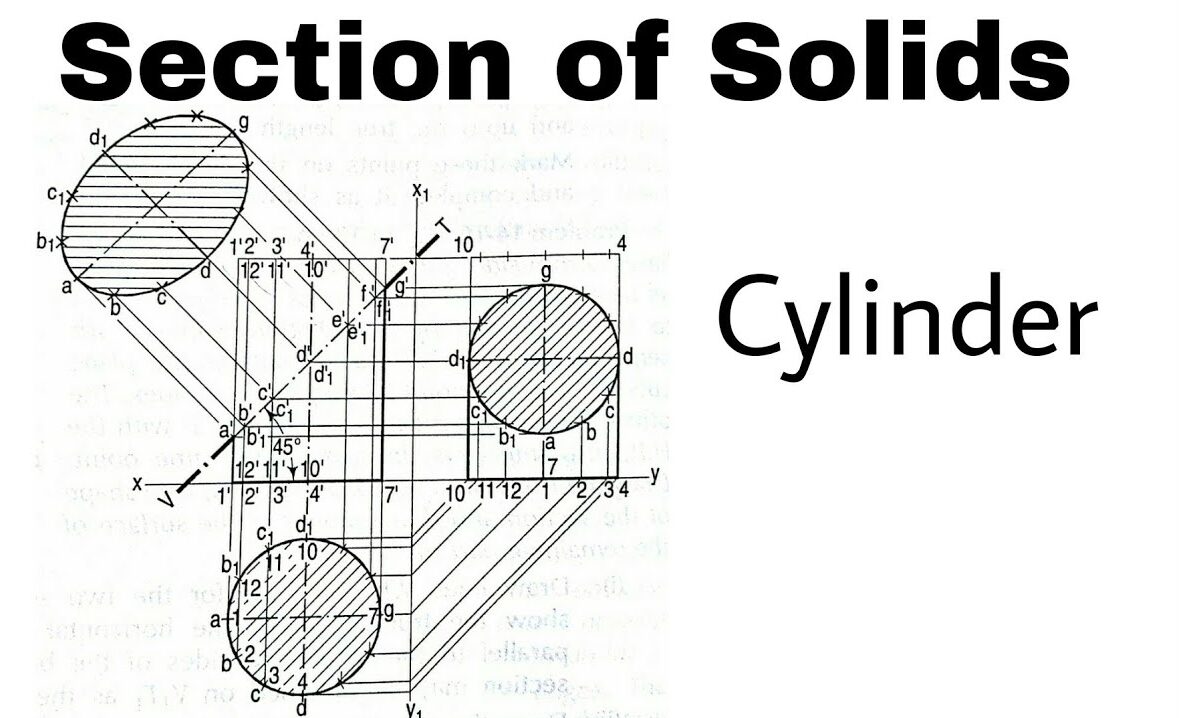
1.2 Example of Sectioning
Example: A cylinder is sectioned by a plane that is:
- Perpendicular to the HP and inclined to the VP.
- The circular base will be shown as an ellipse in the section view.
2. Isometric Projections
Isometric projections provide a three-dimensional representation of an object on a two-dimensional plane, maintaining the scale along the three principal axes.
2.1 Isometric Scale
An isometric scale is used to draw isometric projections. It involves measuring lengths along the axes at 30-degree angles from the horizontal. The scale maintains proportionality among the dimensions of the object.
Isometric Lengths:
- Along the x-axis:
Lx = Lactual - Along the y-axis:
Ly = Lactual - Along the z-axis:
Lz = Lactual
Where Lactual is the actual length of the object along that axis.
2.2 Drawing Isometric Projections from Orthographic Views
To create an isometric projection from given orthographic views:
- Identify the dimensions from the orthographic views.
- Use an isometric scale to represent these dimensions on the isometric drawing.
- Align the dimensions to the three principal axes, ensuring correct angles (30 degrees).
- Complete the drawing by connecting the points to form the solid.
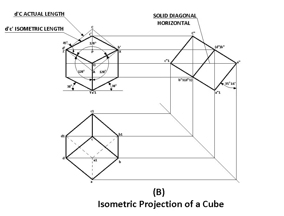
2.3 Example of Isometric Projection
Example: For a cube with an edge length of 50 mm, the isometric projection would be drawn as follows:
- Each edge will measure 50 mm along the isometric scale.
- The angles between the axes will be 120 degrees.
Mastery of sectioning and isometric projections is essential for accurately depicting three-dimensional objects in engineering drawings. These techniques allow for a clear understanding of both external and internal features of solids, facilitating effective communication in technical fields.
Reference/Text Books:
1. N. D. Bhatt, Engineering Drawing, Charotar Publishing House, 46th Edition,2003.
2. K. V. Nataraajan, A text book of Engineering Graphic, Dhanalakshmi
Publishers, Chennai, 2006.
3.K. Venugopal and V. Prabhu Raja, Engineering Graphics, New Age
International (P) Ltd, 2008.
4. DhananjayA.Jolhe,EngineeringDrawingwithanIntroductiontoAutocad,Mc
GrawHill Education, 2017