Basic Electrical and Electronics Engineering
Unit 1: Elementary Electrical Concepts
1. Fundamentals of Electrical Systems
Electrical systems are foundational to modern technology, powering everything from household appliances to industrial machines. To understand these systems, it’s crucial to grasp several fundamental concepts, such as voltage, current, resistance, and the principles governing their interactions.
Potential Difference (Voltage)
Potential difference, commonly known as voltage, is the measure of electric potential energy per unit charge between two points in an electrical circuit. It is this difference in potential that causes electric charges to flow, creating an electric current. Without voltage, no current would flow, and electrical devices would not operate.
Where:
- V = Potential Difference (Volts)
- W = Work Done (Joules)
- Q = Charge (Coulombs)
This formula indicates that the potential difference is equivalent to the amount of work done to move a charge from one point to another. In practical terms, higher voltages can push more current through a conductor, allowing for the operation of larger electrical devices.
Ohm’s Law
Ohm’s Law is one of the most critical principles in electrical engineering. It establishes a relationship between voltage, current, and resistance in a circuit. This law is fundamental in circuit design and analysis, helping engineers determine how much current will flow under a given voltage and resistance.
Where:
- V = Voltage (Volts)
- I = Current (Amperes)
- R = Resistance (Ohms)
According to Ohm’s Law, the current flowing through a conductor between two points is directly proportional to the voltage across those points and inversely proportional to the resistance of the conductor. This means that if you increase the voltage, the current will also increase, assuming resistance remains constant. Conversely, if resistance increases, the current will decrease for a constant voltage.
Effect of Temperature on Resistance
The resistance of materials can significantly change with temperature. For most conductors, as the temperature increases, the resistance also increases. This relationship is crucial for electrical engineers to consider when designing circuits that may operate in varying temperature conditions.
Where:
- R_t = Resistance at temperature T
- R_0 = Resistance at reference temperature T_0
- α = Temperature coefficient of resistance (°C-1)
- T = Current temperature (°C)
- T_0 = Reference temperature (°C)
This formula illustrates how the resistance of a conductor changes with temperature. Understanding this concept is crucial for preventing overheating in circuits and ensuring the reliability of electronic components.
Electrical Wiring System
Electrical wiring systems are essential for safely and effectively distributing electricity throughout homes and industries. Different wire gauges (diameters) are used depending on the application, and choosing the right gauge is critical for ensuring safety and efficiency. Using a wire that is too thin for a given load can result in overheating and potentially cause a fire.
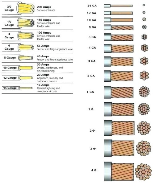
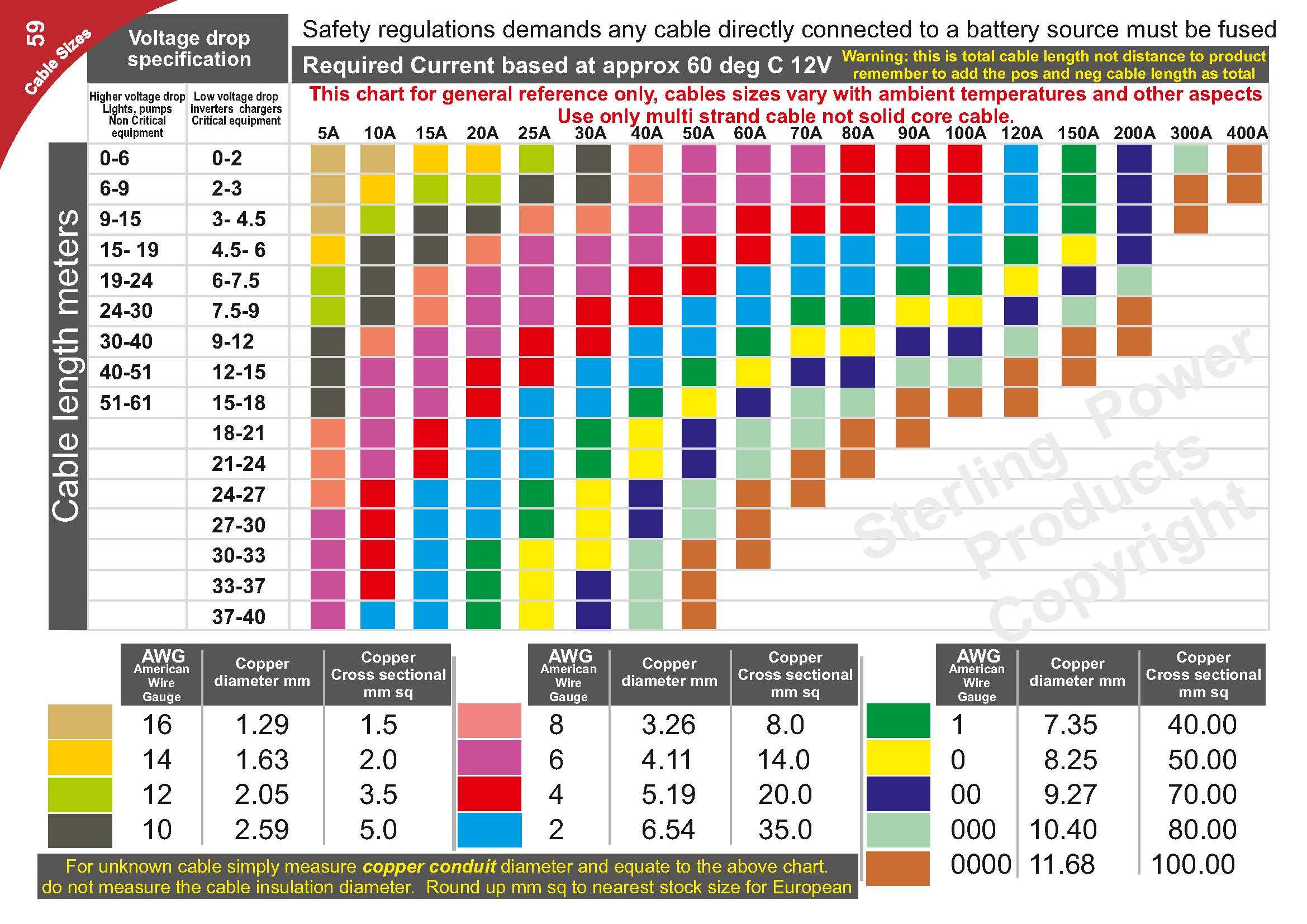
In residential wiring, common gauges include:
- 14 AWG: Generally used for lighting circuits.
- 12 AWG: Commonly employed for general-purpose circuits, such as outlets.
- 10 AWG: Often utilized for heavy-duty appliances, such as air conditioners or water heaters.
In industrial applications, wire selection is determined by load requirements, environmental conditions, and regulatory standards. Properly sizing wires helps to ensure reliable operation and longevity of electrical systems.
2. Energy Resources and Utilization
Conventional and Nonconventional Energy Resources
Energy resources can be broadly classified into two categories: conventional and nonconventional resources. Understanding these categories is essential for sustainable energy management and environmental conservation.
- Conventional Energy Resources: These include fossil fuels like coal, oil, and natural gas, as well as nuclear power. While these sources have been the backbone of energy generation for decades, they are limited and contribute to environmental pollution and climate change.
- Nonconventional Energy Resources: These resources include renewable sources such as solar energy, wind energy, hydroelectric power, and geothermal energy. They are considered more sustainable and environmentally friendly, as they do not deplete natural resources and have a lower environmental impact.
Electrical Energy Generation
Electrical energy can be generated through various methods, each with its own set of advantages and disadvantages. Here are some primary methods:
- Thermal Power Plants: These plants burn fossil fuels to produce steam, which drives turbines to generate electricity. While they can produce large amounts of power, they also release significant greenhouse gases and require careful management of emissions.
- Hydroelectric Plants: Utilizing the flow of water to turn turbines, hydroelectric plants are a clean source of energy. They rely on rivers or dams to create a flow of water, generating electricity without burning fossil fuels.
- Wind Turbines: Wind energy is harnessed through turbines that convert the kinetic energy of wind into electricity. This method is highly sustainable and produces no emissions, but it requires consistent wind conditions and adequate space.
- Solar Power: Photovoltaic cells convert sunlight directly into electricity. Solar panels can be installed on homes or in large solar farms. This technology is rapidly evolving and becoming more cost-effective.
Transmission and Distribution
Once electrical energy is generated, it must be transmitted and distributed to consumers. This process involves a complex network of power lines, substations, and transformers:
- Transmission Lines: These high-voltage lines transport electricity over long distances from power plants to substations. High voltages are used to minimize energy losses during transmission.
- Distribution Lines: After electricity reaches substations, it is transformed to lower voltages suitable for consumer use. Distribution lines then carry this electricity to homes and businesses.
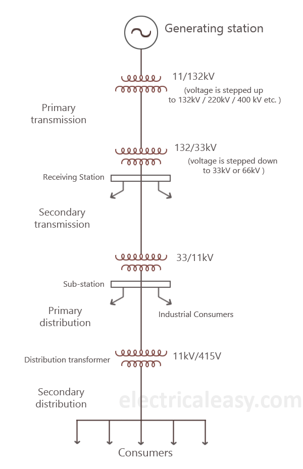
This entire system ensures that electrical energy is available where it is needed, with minimal losses along the way.
Advantages & Disadvantages of AC & DC Transmission
Alternating Current (AC) and Direct Current (DC) are the two main forms of electrical power transmission. Each has its unique advantages and challenges:
- AC Transmission:
- Advantages:
- Voltage Transformation: AC can be easily transformed to different voltage levels using transformers, making it ideal for long-distance transmission.
- Transmission Efficiency: Higher voltages reduce current, leading to lower resistive losses.
- Disadvantages:
- Complex Equipment: AC systems require more complex equipment, such as transformers and circuit breakers.
- Reactive Power Losses: AC systems can suffer from reactive power losses, affecting overall efficiency.
- Advantages:
- DC Transmission:
- Advantages:
- Lower Transmission Losses: Over very long distances, DC can be more efficient than AC.
- Simpler Technology: DC transmission can simplify some aspects of electrical engineering.
- Disadvantages:
- Conversion Cost: Converting AC to DC and vice versa is costly and requires specialized equipment.
- Limited Distance: Historically, DC has been limited to shorter distances, although advancements are changing this.
- Advantages:
Concept of Supply and Demand
The concept of supply and demand is crucial in the field of electrical engineering and energy management. Supply refers to the total amount of electrical energy produced and made available, while demand refers to the total amount of electrical energy consumed by users. Balancing these two factors is essential for maintaining system stability and efficiency.
When demand exceeds supply, it can lead to blackouts or system failures. Conversely, when supply exceeds demand, resources may be wasted. Effective forecasting and management strategies are necessary to ensure that energy production aligns with consumer needs.
Power Factor
The power factor is an essential parameter in electrical systems, indicating the efficiency with which electrical power is converted into useful work output. It is defined as the ratio of real power (measured in watts) to apparent power (measured in volt-amperes).
Where:
- P = Real Power (Watts)
- S = Apparent Power (Volt-Amperes)
A power factor of 1 (or unity) indicates that all the power supplied by the source is being effectively used, while a power factor less than 1 suggests that some energy is wasted in the system. Improving power factor can lead to reduced energy costs and improved performance of electrical systems.
Need for Unity Power Factor
Achieving a unity power factor (PF = 1) is ideal in electrical systems because it indicates maximum efficiency. In practical applications, a unity power factor means that all electrical power supplied is being used effectively without reactive losses. This condition helps reduce energy costs, enhances the lifespan of electrical equ
Unit 1: Elementary Electrical Concepts
1. Fundamentals of Electrical Systems
Electrical systems are foundational to modern technology, powering everything from household appliances to industrial machines. To understand these systems, it’s crucial to grasp several fundamental concepts, such as voltage, current, resistance, and the principles governing their interactions.
Potential Difference (Voltage)
Potential difference, commonly known as voltage, is the measure of electric potential energy per unit charge between two points in an electrical circuit. It is this difference in potential that causes electric charges to flow, creating an electric current. Without voltage, no current would flow, and electrical devices would not operate.
Where:
- V = Potential Difference (Volts)
- W = Work Done (Joules)
- Q = Charge (Coulombs)
This formula indicates that the potential difference is equivalent to the amount of work done to move a charge from one point to another. In practical terms, higher voltages can push more current through a conductor, allowing for the operation of larger electrical devices.
Ohm’s Law
Ohm’s Law is one of the most critical principles in electrical engineering. It establishes a relationship between voltage, current, and resistance in a circuit. This law is fundamental in circuit design and analysis, helping engineers determine how much current will flow under a given voltage and resistance.
Where:
- V = Voltage (Volts)
- I = Current (Amperes)
- R = Resistance (Ohms)
According to Ohm’s Law, the current flowing through a conductor between two points is directly proportional to the voltage across those points and inversely proportional to the resistance of the conductor. This means that if you increase the voltage, the current will also increase, assuming resistance remains constant. Conversely, if resistance increases, the current will decrease for a constant voltage.
Effect of Temperature on Resistance
The resistance of materials can significantly change with temperature. For most conductors, as the temperature increases, the resistance also increases. This relationship is crucial for electrical engineers to consider when designing circuits that may operate in varying temperature conditions.
Where:
- R_t = Resistance at temperature T
- R_0 = Resistance at reference temperature T_0
- α = Temperature coefficient of resistance (°C-1)
- T = Current temperature (°C)
- T_0 = Reference temperature (°C)
This formula illustrates how the resistance of a conductor changes with temperature. Understanding this concept is crucial for preventing overheating in circuits and ensuring the reliability of electronic components.
Electrical Wiring System
Electrical wiring systems are essential for safely and effectively distributing electricity throughout homes and industries. Different wire gauges (diameters) are used depending on the application, and choosing the right gauge is critical for ensuring safety and efficiency. Using a wire that is too thin for a given load can result in overheating and potentially cause a fire.


In residential wiring, common gauges include:
- 14 AWG: Generally used for lighting circuits.
- 12 AWG: Commonly employed for general-purpose circuits, such as outlets.
- 10 AWG: Often utilized for heavy-duty appliances, such as air conditioners or water heaters.
In industrial applications, wire selection is determined by load requirements, environmental conditions, and regulatory standards. Properly sizing wires helps to ensure reliable operation and longevity of electrical systems.
2. Energy Resources and Utilization
Conventional and Nonconventional Energy Resources
Energy resources can be broadly classified into two categories: conventional and nonconventional resources. Understanding these categories is essential for sustainable energy management and environmental conservation.
- Conventional Energy Resources: These include fossil fuels like coal, oil, and natural gas, as well as nuclear power. While these sources have been the backbone of energy generation for decades, they are limited and contribute to environmental pollution and climate change.
- Nonconventional Energy Resources: These resources include renewable sources such as solar energy, wind energy, hydroelectric power, and geothermal energy. They are considered more sustainable and environmentally friendly, as they do not deplete natural resources and have a lower environmental impact.
Electrical Energy Generation
Electrical energy can be generated through various methods, each with its own set of advantages and disadvantages. Here are some primary methods:
- Thermal Power Plants: These plants burn fossil fuels to produce steam, which drives turbines to generate electricity. While they can produce large amounts of power, they also release significant greenhouse gases and require careful management of emissions.
- Hydroelectric Plants: Utilizing the flow of water to turn turbines, hydroelectric plants are a clean source of energy. They rely on rivers or dams to create a flow of water, generating electricity without burning fossil fuels.
- Wind Turbines: Wind energy is harnessed through turbines that convert the kinetic energy of wind into electricity. This method is highly sustainable and produces no emissions, but it requires consistent wind conditions and adequate space.
- Solar Power: Photovoltaic cells convert sunlight directly into electricity. Solar panels can be installed on homes or in large solar farms. This technology is rapidly evolving and becoming more cost-effective.
Transmission and Distribution
Once electrical energy is generated, it must be transmitted and distributed to consumers. This process involves a complex network of power lines, substations, and transformers:
- Transmission Lines: These high-voltage lines transport electricity over long distances from power plants to substations. High voltages are used to minimize energy losses during transmission.
- Distribution Lines: After electricity reaches substations, it is transformed to lower voltages suitable for consumer use. Distribution lines then carry this electricity to homes and businesses.

This entire system ensures that electrical energy is available where it is needed, with minimal losses along the way.
Advantages & Disadvantages of AC & DC Transmission
Alternating Current (AC) and Direct Current (DC) are the two main forms of electrical power transmission. Each has its unique advantages and challenges:
- AC Transmission:
- Advantages:
- Can be easily transformed to different voltage levels, which allows for efficient long-distance transmission.
- Less energy loss over long distances due to the ability to step-up voltages.
- Disadvantages:
- More complex equipment required for transformers and reactive power compensation.
- Potentially more prone to interference and harmonics.
- Advantages:
- DC Transmission:
- Advantages:
- Lower energy losses over long distances and no phase issues.
- Simpler system with fewer components needed.
- Disadvantages:
- More expensive to convert to AC for use in homes and businesses.
- Limited to shorter distances unless high-voltage DC technology is employed.
- Advantages:
3. Electrical Measurements
Accurate electrical measurements are essential for designing and maintaining electrical systems. Various instruments are used to measure different electrical parameters:
- Voltmeters: Used to measure voltage across components.
- Ammeters: Measure current flowing through a circuit.
- Ohmmeters: Measure resistance in a circuit.
Understanding how to use these instruments correctly ensures that electrical systems operate safely and effectively.
Measuring Instruments
The following instruments are commonly used in electrical measurements:
- Multimeter: A versatile tool that can measure voltage, current, and resistance.
- Clamp Meter: Used for measuring current without interrupting the circuit. It “clamps” around a wire to measure the magnetic field produced by the current.
- Oscilloscope: Visualizes electrical signals over time, allowing engineers to analyze waveforms and signal integrity.
Safety Considerations
When conducting electrical measurements, safety is paramount. Here are key safety practices:
- Always ensure the instrument is rated for the voltage being measured.
- Use insulated tools and wear appropriate personal protective equipment (PPE).
- Be cautious of live circuits and avoid touching conductive materials while measuring.
Understanding elementary electrical concepts is crucial for anyone working in or studying electrical engineering. From voltage and current to the methods of generation and transmission, these principles lay the groundwork for more advanced topics in electrical systems. As technology evolves, staying informed about these concepts will remain vital for innovation and sustainability in energy management.
ipment, and decreases the environmental impact of energy production.
Various techniques, such as power factor correction devices, are employed to improve power factor in industrial and commercial settings. These devices can help mitigate the effects of inductive loads, which are common in motors and transformers, contributing to a lower power factor.
Unit 2: Measurement of Electrical Quantities
1. Measurement of Voltage, Current, and Power
Measuring electrical quantities is essential for diagnosing, maintaining, and optimizing electrical systems. Understanding how to measure voltage, current, and power allows engineers and technicians to ensure that electrical systems operate efficiently and safely. Each measurement technique has its own principles and applications, making it crucial to comprehend these aspects thoroughly.
Measurement of Voltage
Voltage is defined as the electrical potential difference between two points in a circuit. It is a measure of how much potential energy exists to move electric charge and is measured in volts (V). A voltmeter is used to measure voltage, and it can be either analog or digital. When connecting a voltmeter, it is crucial to connect it in parallel with the component whose voltage is to be measured to obtain an accurate reading.
Analog voltmeters utilize a needle and dial to indicate voltage levels, whereas digital voltmeters provide numerical readouts, making them easier to interpret. It’s important to ensure that the voltmeter’s range is set appropriately to prevent damage and ensure accurate measurements.
In this equation, V represents voltage, I is current, and R is resistance, according to Ohm’s Law. This law highlights the direct relationship between voltage, current, and resistance in a circuit. Understanding voltage measurement is crucial for troubleshooting electrical systems and ensuring components operate within their specified voltage ratings.
Measurement of Current
Current is the flow of electric charge in a circuit, measured in amperes (A). An ammeter is used to measure current and must be connected in series with the circuit component to ensure that the full current passes through the meter. Like voltmeters, ammeters can be analog or digital. The choice of ammeter depends on the expected current levels; using an inappropriate range can damage the device or yield inaccurate readings.
Analog ammeters typically use a needle that moves across a scale, while digital ammeters display numerical values, making it easier to read and record data. Proper current measurement is vital for ensuring the safety and functionality of electrical devices.
This formula, derived from Ohm’s Law, allows us to calculate current if voltage and resistance are known. Understanding how to measure current is essential for various applications, including checking the load on circuits and assessing the performance of electrical appliances.
Measurement of Power
Power is defined as the rate at which electrical energy is consumed or produced and is measured in watts (W). It is a critical parameter in electrical systems as it reflects the effectiveness of energy usage. The power in an electrical circuit can be calculated using the following formula:
Where:
- P = Power (Watts)
- V = Voltage (Volts)
- I = Current (Amperes)
- cos(φ) = Power Factor (dimensionless)
This equation shows that power depends not only on voltage and current but also on the phase difference between them, represented by the power factor (cos(φ)). A power factor of 1 indicates that all the power supplied is being effectively used, whereas a power factor less than 1 suggests that some energy is wasted in the system. Accurate power measurement is critical for assessing energy consumption and improving efficiency.
2. Measurement of 3-Phase Power
Three-phase power systems are widely used in industrial and commercial applications due to their efficiency in delivering power. The measurement of three-phase power can be done using various methods, depending on the configuration of the system. Understanding how to measure three-phase power is essential for managing large electrical loads effectively.
Types of 3-Phase Systems
Three-phase systems can be configured in either delta (Δ) or star (Y) connections. Each configuration affects the voltage and current relationships differently:
- Delta Connection: In a delta connection, each phase is connected end-to-end in a loop, forming a closed triangular circuit. The line voltage (V_L) is equal to the phase voltage (V_P), while the line current (I_L) is √3 times the phase current (I_P).
- Star Connection: In a star connection, one terminal of each phase is connected to a common point (neutral), and the other terminal is connected to the supply lines. Here, the line voltage is √3 times the phase voltage, while the line current is equal to the phase current.
Measurement Methods
Power can be measured in three-phase systems using either:
- Two-Wattmeter Method: In this method, two wattmeters are used to measure the power in the three-phase system. The total power can be calculated by summing the readings of the two wattmeters. This method is suitable for both balanced and unbalanced loads, making it versatile for various applications.
- Three-Wattmeter Method: This method involves using three wattmeters, one for each phase. The total power is the sum of the readings from all three wattmeters. This method provides a more accurate measurement, especially in unbalanced loads, and is commonly used in complex industrial systems.
3. Study of Energy Meters
Energy meters, also known as watt-hour meters, are devices used to measure the amount of electrical energy consumed by a circuit over a specified period. These meters are essential for billing and monitoring energy usage in residential, commercial, and industrial settings.
Types of Energy Meters
- Electromechanical Meters: These traditional meters utilize rotating disks to measure energy consumption. The disk rotates proportionally to the amount of electricity consumed, which is then translated into readings on the dial. Electromechanical meters are durable and have been widely used for decades, but they are less precise compared to modern alternatives.
- Electronic Energy Meters: These modern meters use digital displays and advanced electronics to measure and record energy usage. They often include features like time-of-use pricing, data logging, and remote monitoring capabilities. Electronic meters provide higher accuracy, improved functionality, and the ability to communicate with utility companies for smart grid applications.
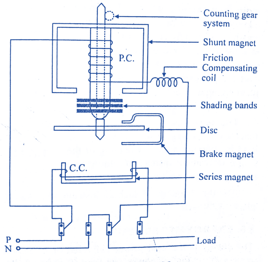
Energy meters are critical for understanding energy consumption patterns, allowing users to identify opportunities for energy savings and better manage their energy usage.
4. Study of Electrical Storage Devices
Electrical storage devices play a crucial role in energy management, allowing for the storage and discharge of electrical energy as needed. This capability is especially important for balancing supply and demand, especially in renewable energy systems. Here, we will examine some common types of batteries.
1. Nickel-Cadmium (NiCd) Batteries
NiCd batteries are rechargeable batteries that use nickel oxide hydroxide and metallic cadmium as electrodes. They are known for their durability and ability to deliver high discharge rates, making them suitable for applications like power tools, emergency lighting, and various portable devices. However, their use has declined in favor of newer battery technologies.
- Advantages: NiCd batteries have a long cycle life and can withstand deep discharges. They perform well at low temperatures, which makes them ideal for outdoor applications. Furthermore, they can be charged rapidly, reducing downtime.
- Disadvantages: Environmental concerns arise due to cadmium’s toxicity, requiring careful disposal. Additionally, NiCd batteries exhibit a memory effect, which can reduce the usable capacity if they are repeatedly partially discharged before being recharged.
2. Lithium-Ion (Li-ion) Batteries
Li-ion batteries are widely used in consumer electronics, electric vehicles, and renewable energy storage systems due to their high energy density and lightweight nature. They work by transferring lithium ions between the anode and cathode during charging and discharging cycles, allowing for efficient energy storage and release.
- Advantages: Li-ion batteries offer a high energy-to-weight ratio, longer lifespan, and minimal self-discharge. They also do not suffer from the memory effect, making them more convenient for users.
- Disadvantages: Li-ion batteries can be sensitive to extreme temperatures and may pose safety risks if damaged. They also require advanced battery management systems to optimize performance and prolong life.
3. Lithium Polymer (Li-pol) Batteries
Li-pol batteries are a variant of lithium-ion technology, featuring a flexible, polymer electrolyte that allows for lighter and thinner designs. They are often used in applications requiring low weight and high performance, such as drones, smartphones, and wearables.
- Advantages: Li-pol batteries are lightweight, versatile in shape, and can be made thinner than traditional Li-ion batteries. They also offer higher discharge rates, which is beneficial for high-performance applications.
- Disadvantages: Li-pol batteries can be more expensive than other types and may require additional safety measures to prevent swelling or damage.
5. Study of Electrical Installations
Electrical installations involve the arrangement and setup of electrical components for residential, commercial, and industrial applications. Proper installation is crucial for ensuring safety, reliability, and efficiency in electrical systems.
Types of Electrical Installations
- Residential Installations: These involve wiring and connecting electrical devices in homes, including lighting, power outlets, and appliances. Safety codes must be followed to prevent hazards.
- Commercial Installations: In commercial settings, electrical installations are designed for larger systems, including HVAC, lighting, and power distribution for various equipment. These installations require careful planning and adherence to building codes.
- Industrial Installations: These installations often involve complex systems for manufacturing processes, heavy machinery, and specialized equipment. They require significant expertise and must comply with strict safety regulations.
Safety Considerations
Ensuring safety in electrical installations is paramount. Key safety measures include:
- Proper grounding to prevent electrical shock.
- Using circuit breakers and fuses to protect against overloads and short circuits.
- Following national and local electrical codes and standards.
- Regular inspection and maintenance of electrical systems to identify potential hazards.

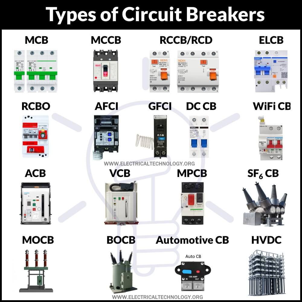
Circuit breakers are essential for maintaining the safety and reliability of electrical systems, acting as a first line of defense against faults and preventing potential hazards.
Actuators
Actuators are devices that convert electrical energy into mechanical motion. They are used to control or operate systems in response to electrical signals. Common types of actuators include:
- Power Contactors: These are electrically-controlled switches used to manage the flow of electricity to motors or other heavy loads. They can handle high currents and are often used in industrial applications.
- Auxiliary Contactors: These contactors are used in conjunction with main contactors to provide additional control options, such as signaling and monitoring. They enhance the flexibility of control systems.
- Electromechanical Relays: These relays use electromagnetic forces to open or close contacts, allowing them to control larger loads using small control signals. They are commonly used for switching and controlling circuits.
- Solid-State Relays: Unlike electromechanical relays, solid-state relays use semiconductor devices to perform switching functions. They offer faster switching times, longer life, and reduced electromagnetic interference.
Understanding the operation and application of circuit breakers and actuators is crucial for designing safe and efficient electrical systems, especially in complex industrial environments.
Unit 3: Diodes and Circuits
1. The P-N Junction Diode
The P-N junction diode is a fundamental semiconductor device that allows current to flow in one direction while blocking it in the opposite direction. This property is crucial for various applications in electronic circuits, particularly in rectification.
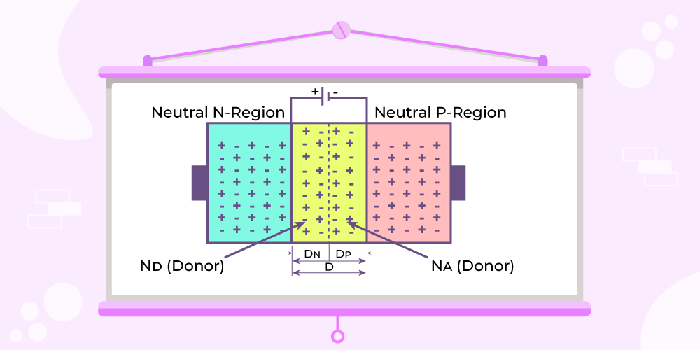
A P-N junction is formed by bringing together p-type and n-type semiconductors. The p-type semiconductor has an abundance of holes (positive charge carriers), while the n-type semiconductor has an excess of electrons (negative charge carriers). When these materials are joined, electrons from the n-type region diffuse into the p-type region, recombining with holes and creating a depletion region that acts as a barrier to current flow.
When a forward voltage is applied, the barrier is reduced, allowing current to flow. Conversely, applying a reverse voltage increases the barrier, preventing current flow.
2. V-I Characteristics
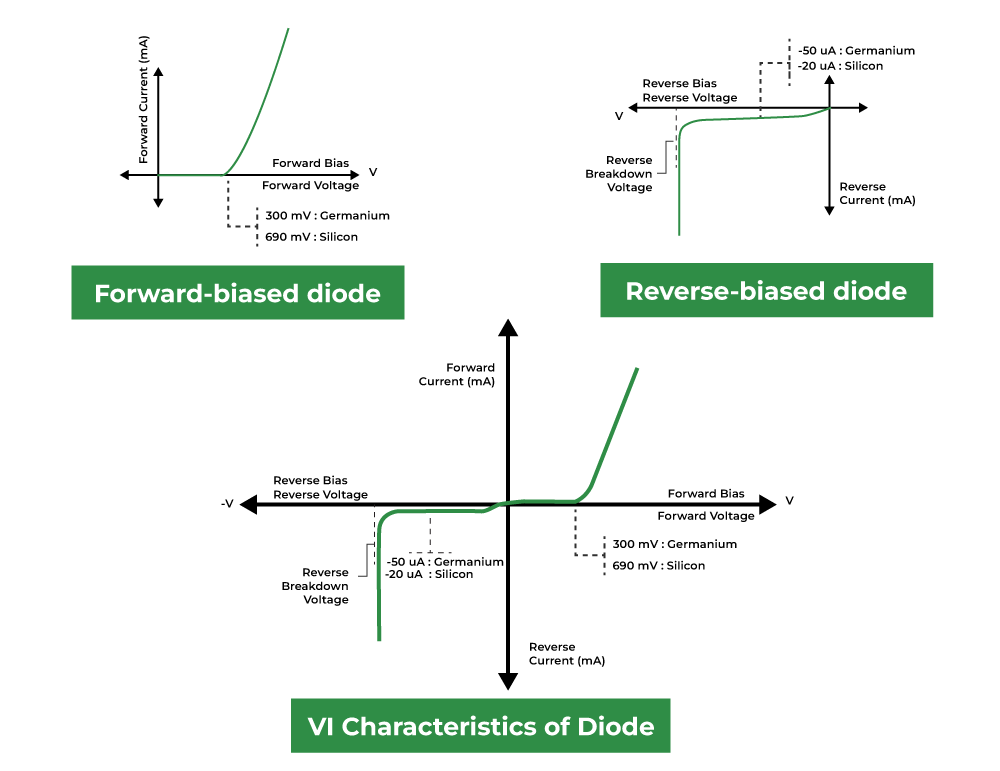
The voltage-current (V-I) characteristics of a P-N junction diode illustrate its behavior under different voltage conditions. This graph shows how the current through the diode varies with the applied voltage.
- Forward Bias: In this mode, when the applied voltage is greater than the threshold (approximately 0.7V for silicon diodes), the diode conducts, and the current increases exponentially.
- Reverse Bias: When a reverse voltage is applied, only a small leakage current flows until breakdown occurs, at which point the diode can conduct in reverse, which can damage the device if not controlled.
3. Diode as Rectifier
Diodes are commonly used as rectifiers to convert alternating current (AC) to direct current (DC). This process is essential in power supply applications, where devices require a steady DC voltage.
Specifications of Rectifier Diodes
When selecting rectifier diodes, several specifications must be considered:
- Peak Inverse Voltage (PIV): The maximum reverse voltage the diode can withstand without breaking down.
- Forward Current (IF): The maximum current the diode can conduct in the forward direction without damage.
- Forward Voltage Drop (VF): The voltage drop across the diode when it is conducting.
- Surge Current Rating: The maximum current the diode can tolerate for a short period without failure.
4. Types of Rectifiers
Rectifiers can be classified into several types based on their configuration:
Half Wave Rectifier
A half wave rectifier uses a single diode to convert AC to DC. During the positive half-cycle of the input AC signal, the diode conducts, allowing current to flow. During the negative half-cycle, the diode is reverse-biased and does not conduct. This results in a pulsating DC output.
The average DC output current (IDC) is a fraction of the peak current (Imax) of the input AC signal.
Full Wave Rectifier
A full wave rectifier uses two or four diodes (in a bridge configuration) to convert both halves of the AC waveform into DC. This results in a smoother output compared to half wave rectification.
In a full wave rectifier, the average DC output current is higher because both halves of the AC waveform are utilized.
Bridge Rectifier
A bridge rectifier consists of four diodes arranged in a bridge configuration. It allows for full-wave rectification using a single transformer secondary winding, providing an efficient conversion of AC to DC.
The average DC output voltage (VDC) is derived from the peak voltage of the AC signal.
Equations for IDC, VDC, VRMS, IRMS, Efficiency, and Ripple Factor
The following equations describe key parameters in rectifier configurations:
- Half Wave Rectifier:
- VDC = Vmax / 2
- VRMS = Vmax / 2
- IRMS = Imax / 2
- Efficiency (η) = (0.406 * VDC) / Vmax
- Ripple Factor (r) = 1.57
- Full Wave Rectifier:
- VDC = Vmax / π
- VRMS = Vmax / √2
- IRMS = Imax / √2
- Efficiency (η) = (0.812 * VDC) / Vmax
- Ripple Factor (r) = 0.48
- Bridge Rectifier:
- VDC = 2 * Vmax / π
- VRMS = Vmax / √2
- IRMS = Imax / √2
- Efficiency (η) = (0.812 * VDC) / Vmax
- Ripple Factor (r) = 0.48
5. Filters
Filters are used in power supply circuits to smooth the output voltage from rectifiers, reducing the ripple and providing a more stable DC voltage. Different types of filters can be employed based on the application requirements:
Capacitor Filter
A capacitor filter uses a capacitor to store charge and release it when the rectified voltage drops. This provides a smoother output voltage by reducing ripple.
Where C is the capacitance, Iload is the load current, and t is the time duration of the ripple.
Choke Input Filter
Choke input filters use an inductor (choke) to smooth the output. The inductor resists changes in current, providing a steady output. This type of filter is effective for applications requiring low ripple.
Capacitor Input Filter (Π Filter)
The Π filter configuration includes capacitors and an inductor to achieve high filtering efficiency. It offers excellent ripple reduction and is commonly used in power supplies.
6. Zener Diode
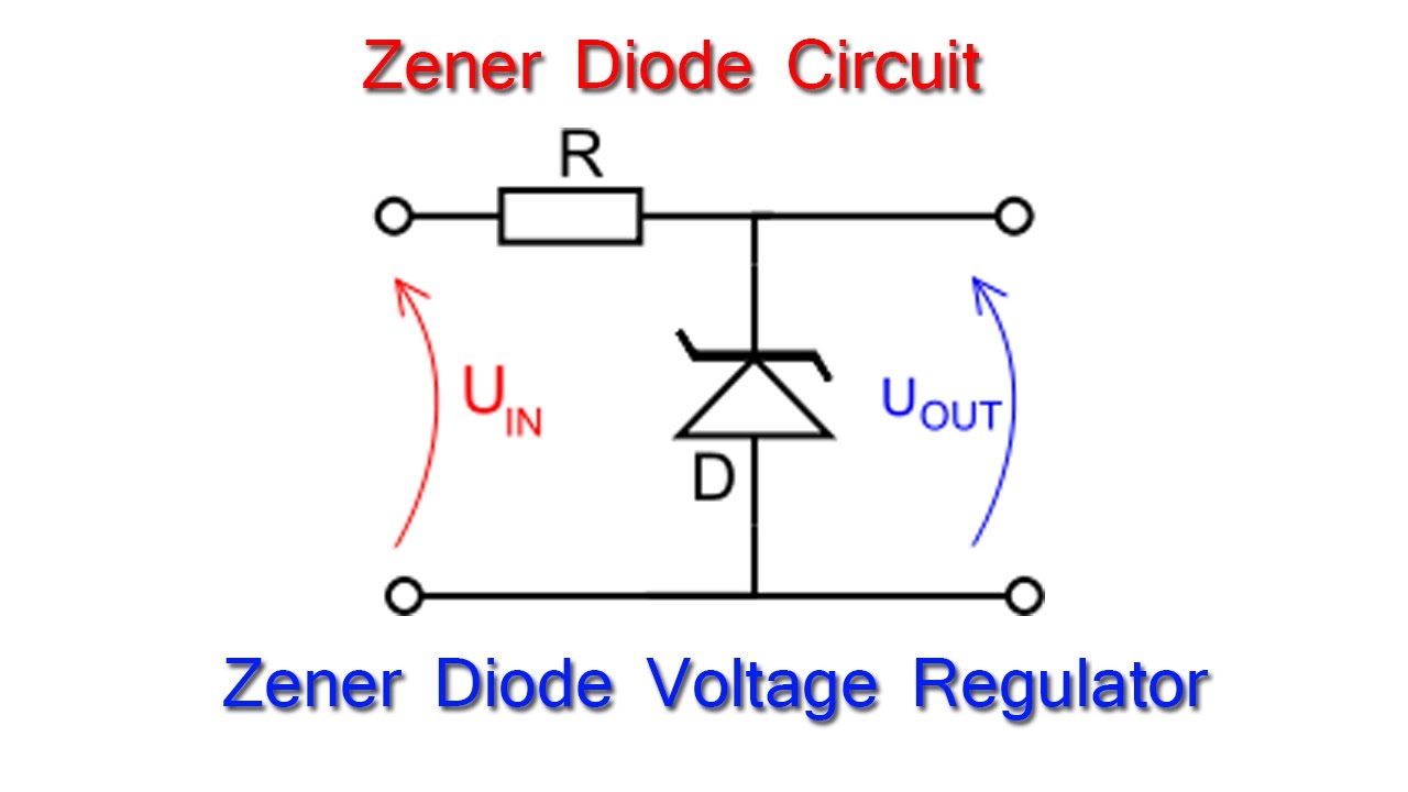
Zener diodes are specialized diodes designed to allow current to flow in the reverse direction when a specified voltage (Zener voltage) is reached. They are used primarily for voltage regulation in circuits.
Characteristics and Specifications
The characteristics of a Zener diode include:
- Zener Voltage (VZ): The voltage at which the diode begins to conduct in reverse.
- Maximum Zener Current (IZ(max)): The maximum current the diode can handle in the Zener region without damage.
- Power Rating: The maximum power the diode can dissipate, calculated as VZ * IZ.
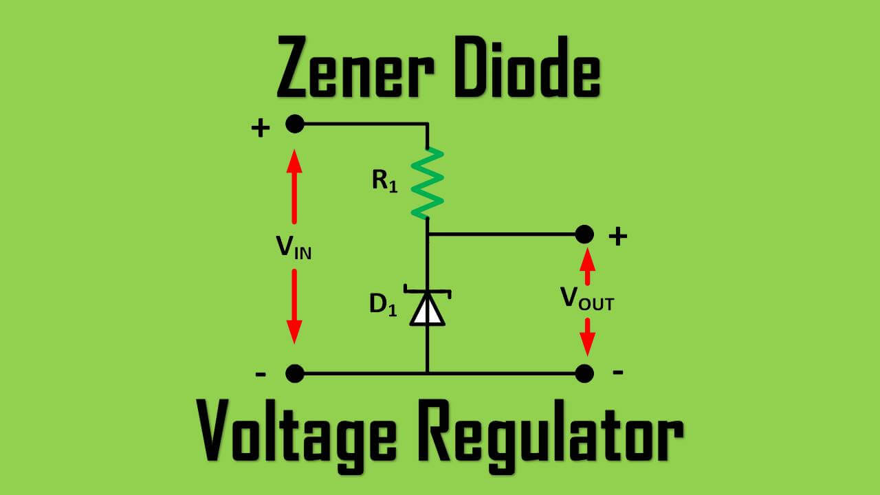
Zener Voltage Regulator
In voltage regulation applications, a Zener diode is connected in reverse bias across the load. It maintains a constant output voltage despite variations in load current or input voltage, making it ideal for providing stable voltage levels.
7. Types of Diodes
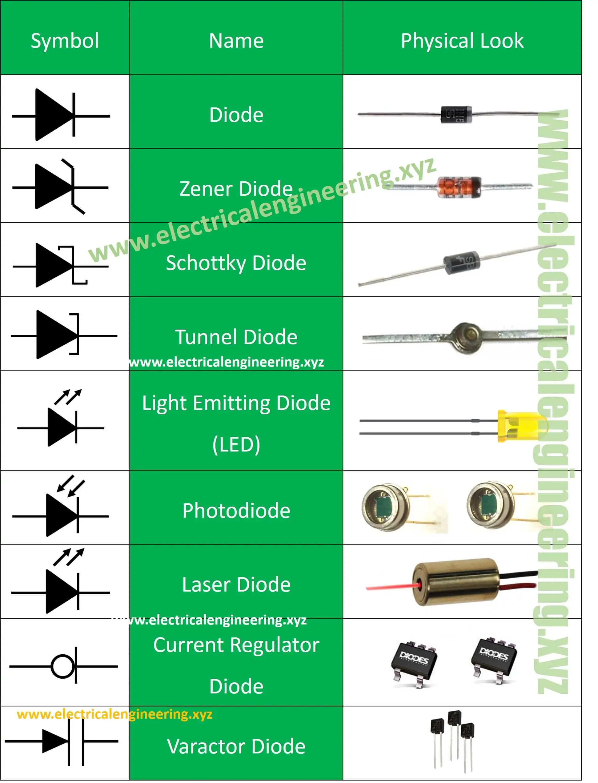 Diodes come in various forms, each tailored for specific applications. Some common types include:
LED (Light Emitting Diode)
LEDs are diodes that emit light when an electric current passes through them. They are energy-efficient, have a long lifespan, and are used in a wide range of applications, from indicators to display screens.
Photodiode
Photodiodes are designed to convert light into electrical current. They are widely used in optical applications, including light sensing and communication systems. Their response time is rapid, making them suitable for high-speed applications.
Unit 4: Semiconductor Devices and Applications
1. Transistors
A transistor is a semiconductor device used to amplify or switch electronic signals and electrical power. Transistors are crucial in modern electronics, serving as the building blocks of integrated circuits and a variety of applications.
1.1 Introduction
Transistors are made from semiconductor materials such as silicon and germanium. They can be classified into two main types: Bipolar Junction Transistors (BJTs) and Field-Effect Transistors (FETs). This unit will focus primarily on BJTs, which are widely used due to their versatility and performance.
1.2 Classification of Transistors
Transistors are classified based on their construction and operation:
- Bipolar Junction Transistor (BJT): Uses both electron and hole charge carriers. It is further classified into NPN and PNP types.
- Field Effect Transistor (FET): Uses only one type of charge carrier (either electrons or holes). It includes MOSFETs and JFETs.
1.3 Configurations
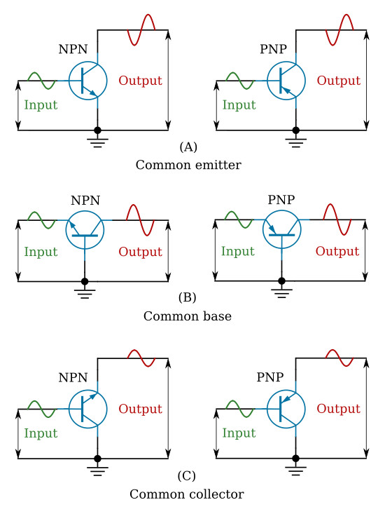
BJTs can be connected in three different configurations: Common Emitter (CE), Common Base (CB), and Common Collector (CC). Each configuration has unique characteristics and applications:
- Common Emitter (CE): Provides voltage gain and phase inversion. It is the most commonly used configuration for amplifiers.
- Common Base (CB): Provides low input impedance and high output impedance. It is typically used in high-frequency applications.
- Common Collector (CC): Also known as an emitter follower, it provides current gain and is used for impedance matching.
1.4 Parameters: α and β
The performance of a BJT is characterized by two important parameters: α (alpha) and β (beta).
- α (Alpha): The ratio of the collector current (IC) to the emitter current (IE):α = IC / IE
Alpha indicates how much of the emitter current contributes to the collector current.
- β (Beta): The ratio of the collector current to the base current (IB):β = IC / IB
Beta is a measure of the transistor’s amplification capability.
1.5 Gain and Bandwidth
The gain of a transistor refers to its ability to amplify an input signal. The bandwidth is the range of frequencies over which the transistor can effectively amplify a signal. Both parameters are crucial for selecting a transistor for specific applications.
2. Operation of BJT
Understanding the operation of BJTs involves analyzing their behavior in different regions:
2.1 Cut-off Region
In the cut-off region, the base-emitter junction is reverse-biased, and the transistor is essentially turned off. No current flows from collector to emitter, and it acts as an open switch.
2.2 Saturation Region
In the saturation region, both the base-emitter and base-collector junctions are forward-biased. The transistor is fully on, allowing maximum current to flow from collector to emitter, functioning like a closed switch.
2.3 Active Region
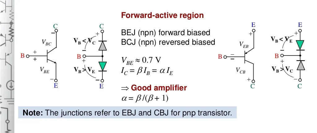
In the active region, the base-emitter junction is forward-biased, and the base-collector junction is reverse-biased. The transistor operates as an amplifier in this region, allowing a small change in base current to produce a significant change in collector current.
2.4 DC Analysis
DC analysis of BJTs involves calculating the DC operating point (Q-point) to ensure the transistor operates efficiently in the desired region. This analysis is crucial for biasing techniques.
2.5 BJT as an Amplifier
When configured as an amplifier, the BJT increases the amplitude of a weak input signal. The output signal is typically larger than the input, maintaining the same waveform shape but with increased voltage and current levels.
2.6 Biasing Techniques
Biasing is essential to set the Q-point of the BJT for stable operation. Common biasing techniques include:
- Fixed Bias: A simple method that uses a single resistor to provide a biasing current.
- Collector Feedback Bias: Uses feedback from the collector to stabilize the operating point.
- Voltage Divider Bias: Utilizes two resistors to set a stable bias voltage at the base.
2.7 BJT as a Switch
In switching applications, BJTs can be used to turn a circuit on or off. When driven into saturation, they allow maximum current flow, while in the cut-off region, they prevent current flow.
3. Introduction to Digital Electronics
Digital electronics form the backbone of modern computing and communication systems. This section covers fundamental concepts in digital electronics.
3.1 Number System
The number system is a way to represent values. The most common systems include:
- Binary (Base 2): Uses only two digits, 0 and 1, to represent all values. It is the foundation of digital electronics.
- Decimal (Base 10): The standard number system using digits from 0 to 9.
- Hexadecimal (Base 16): Uses sixteen symbols (0-9 and A-F) to represent values, often used in programming and computing.
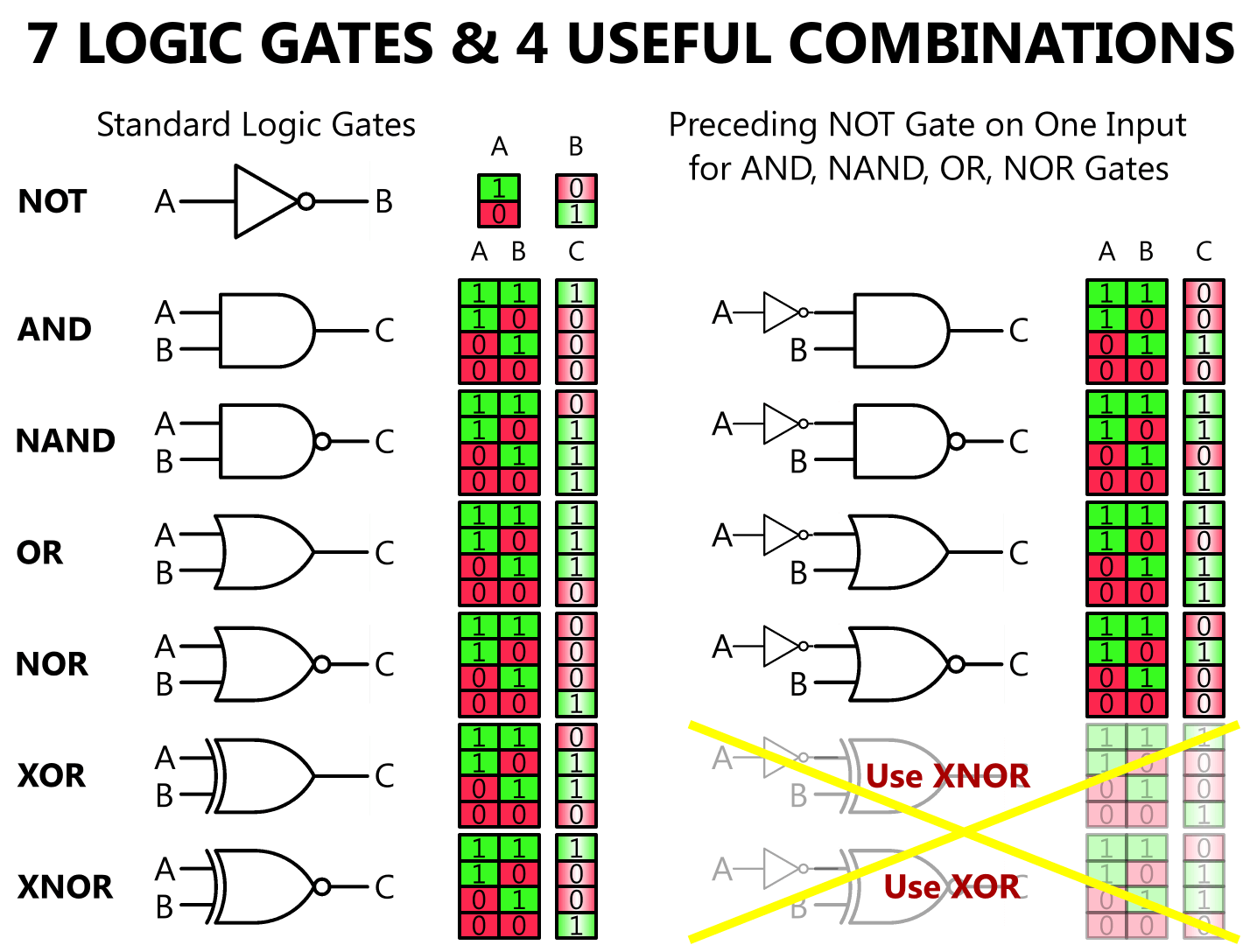
3.2 Basic Logic Gates
Logic gates are the fundamental building blocks of digital circuits, performing basic logical functions. The primary gates include:
- AND Gate: Outputs true (1) only if all inputs are true.
- OR Gate: Outputs true if at least one input is true.
- NOT Gate: Outputs the inverse of the input.
3.3 Universal Gates
Universal gates, such as NAND and NOR gates, can be combined to create any other type of gate. They are essential for designing complex digital circuits.
- NAND Gate: Outputs false only when all inputs are true.
- NOR Gate: Outputs true only when all inputs are false.
3.4 Boolean Postulates
Boolean algebra provides a mathematical framework for analyzing and simplifying logic circuits. Key postulates include:
- Identity Law: A + 0 = A and A · 1 = A
- Null Law: A + 1 = 1 and A · 0 = 0
- Idempotent Law: A + A = A and A · A = A
3.5 De Morgan’s Theorems
De Morgan’s Theorems provide essential rules for transforming and simplifying Boolean expressions:
- (A · B)’ = A’ + B’
- (A + B)’ = A’ · B’
This unit has provided an in-depth overview of semiconductor devices, focusing on transistors and their applications in both analog and digital electronics. Understanding these fundamental concepts is essential for further studies in electronics and electrical engineering.
Reference/Text Books:
1. V. N. Mittal and Arvind Mittal, Basic Electrical Engineering, McGraw-HillPublication.
2. Brijesh Iyer and S. L. Nalbalwar, A Text book of Basic Electronics, Synergy
Knowledgeware Mumbai, 2017.ISBN:978-93-8335-246-3
3. Vincent DelToro, Electrical engineering Fundamentals, PHI Publication, 2nd Edition,2011.
4. Boylstad, Electronics Devices and Circuits Theory, PearsonEducation.
5. Edward Hughes, Electrical Technology, PearsonEducation.
6. D. P. Kothari and Nagrath, Theory and Problems in Electrical Engineering, PHI
Publication,2011.
7. B. L. Theraja, Basic Electronics, S. Chand Limited,2007.
8. Millman Halkias, Integrated Electronics-Analog and Digital Circuits and Systems,
McGraw-Hill Publication,2000.
9. Donald Neaman, Electronic Circuit Analysis and Design, McGraw-Hill Publication,
3rd Edition.
10. Donald Neaman, Electronic Circuit Analysis and Design, McGraw-Hill Publication,
3rd Edition.
11. Printed Circuit Boards Design &Technology,WalterC. Bosshart, McGraw-Hill
Publication.
Note: Students are advised to use internet resources whenever required
